
Optical fiber sensor network for multicomponent gases

An optical fiber sensing, multi-component technology, applied in the measurement of color/spectral characteristics, etc., can solve the problems of unfavorable site simplification, scale, increase the difficulty of input cost management, and difficult sensing and detection operations, etc. Easy to implement, simplified complexity, good economic effect

Active Publication Date: 2015-02-04
WUHAN UNIV OF TECH
View PDF4 Cites 0 Cited by
  • Summary
  • Abstract
  • Description
  • Claims
  • Application Information

AI Technical Summary

Problems solved by technology

[0005] However, since lasers with different wavelengths are required to detect different gases, most of the existing optical fiber gas sensors are self-contained systems, that is, different sensor probes are used to detect different gases, and a set of signal processing systems are used by themselves. This separate detection method It is not economical, and the installation site is complicated, which is not conducive to the simplification and scale of the site
Especially in complex working conditions (such as underground coal mines), the operation of sensing and detecting various gases is difficult, and multi-point, long-distance transmission detection increases the initial investment cost (such as laying a large number of optical cables) and later management difficulties (such as sensor adjustment and maintenance)

Method used


Image

  • Optical fiber sensor network for multicomponent gases
  • Optical fiber sensor network for multicomponent gases

Examples


Embodiment Construction

[0016] The specific embodiments of the present invention will be further described below in conjunction with the accompanying drawings.

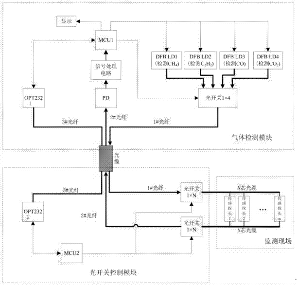
[0017] Such as figure 1 As shown, the multi-component gas optical fiber sensing network consists of three parts: gas detection module, optical switch control module and sensing probe network. The gas detection module can be placed in the monitoring center, away from the monitoring site, where the DFB laser emits laser light corresponding to the absorption wavelength of the corresponding gas to the sensor probe, and performs photoelectric conversion, signal processing and display on the collected optical signal, and the microprocessor 1 Control and integrate the operation of the entire system. The optical switch control module can be placed in a safe area close to the monitoring site, which mainly includes: microprocessor 2 communicates with microprocessor 1 through RS232 to optical fiber device 2 (OPT232-2), and controls two 1×N optical swi...


PUM


Abstract

An optical fiber sensor network for multicomponent gases comprises a first microprocessor, a 1*4 optical switch, four DFB (distributed feedback) lasers with different wavelengths, a photodiode, two RS232-optical fiber converting devices, a signal processing circuit, a second microprocessor, two 1*N optical switches and N sensing probes, wherein the first microprocessor is communicated with the second microprocessor through the RS232-optical fiber converting devices, controls synchronous switch of the two 1*N optical switches, and enables a first optical fiber and a second optical fiber to be communicated with optical fibers at two ends of a first sensing probe; simultaneously, the 1*4 optical switch switches to enable laser spectrums emitted by the DFB lasers with different wavelengths to enter the first optical fiber in a time-sharing manner to be sent to the first sensing probe, and the second optical fiber receives optical signals containing gas concentration information and sends the signals back for processing and analysis, thereby achieving detection of concentrations of a plurality of gases at the first sensing probe; and switching is performed sequentially on every sensing probe for the detection of the concentrations of the plurality of gases. The optical fiber sensor network is suitable for detection of multicomponent gases in flammable and combustible environments, and is good in economy.

Description

technical field [0001] The invention belongs to the technical field of gas concentration detection, in particular to a multi-component gas optical fiber sensing network, which is suitable for real-time detection of various gas concentrations in industrial environments. technical background [0002] Toxic, harmful, flammable and explosive gases emitted during industrial production pose a serious threat to environmental pollution and production safety. Leakage, discharge and distribution, and take effective control measures. [0003] There are many types of existing gas concentration detection technologies. The traditional electrochemical gas concentration measurement method has shortcomings such as short life, low precision, slow response, poor stability, difficult adjustment, and poor gas selectivity. There are potential safety hazards when used in explosive and other industrial environments. Optical gas sensing technology is an emerging gas detection technology. This tech...

Claims


Application Information

Patent Timeline
Patent Type & Authority Patents(China)
IPC IPC(8): G01N21/31
Inventor 李政颖王洪海王立新谭玖孙文丰
Owner WUHAN UNIV OF TECH
Learn More