Projection objective wave aberration on-line detection device and method based on double-beam interference

A technology of projection objective lens and detection device, which is applied in the direction of exposure device for photoengraving process, testing optical performance, exposure equipment for microlithography, etc. Process, the effect of improving measurement accuracy

Inactive Publication Date: 2013-05-01
INST OF MICROELECTRONICS CHINESE ACAD OF SCI
View PDF15 Cites 7 Cited by
  • Summary
  • Abstract
  • Description
  • Claims
  • Application Information

AI Technical Summary

Problems solved by technology

[0007] The technical problem to be solved by the present invention is to propose an online measurement device and method for the wave aberration of the projection objective lens of a lithography machine, so as to overcome the existing technology that can only measure the low-level aberration of the projection objective lens, or can measure all image aberrations. Poor but the measurement process and method are complicated

Method used


Image

  • Projection objective wave aberration on-line detection device and method based on double-beam interference
  • Projection objective wave aberration on-line detection device and method based on double-beam interference
  • Projection objective wave aberration on-line detection device and method based on double-beam interference

Examples


Embodiment 1

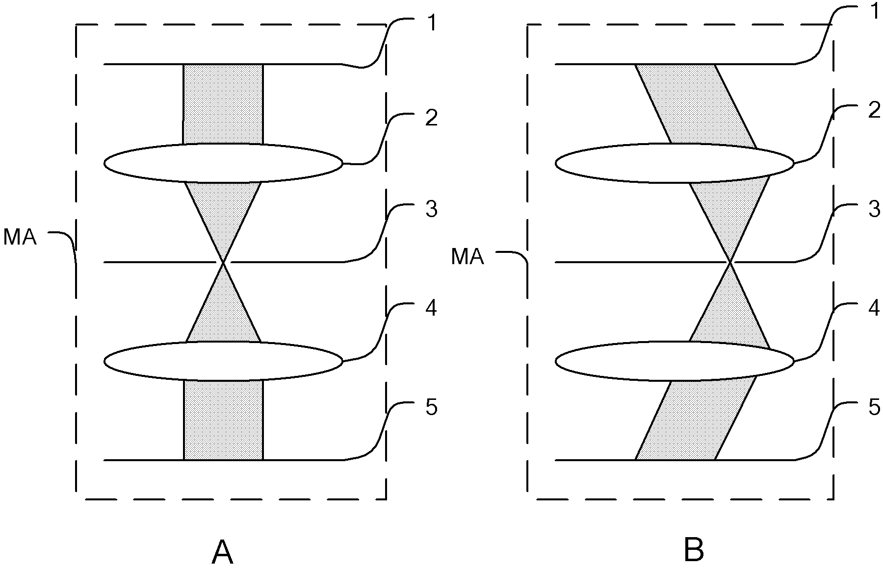
[0026] figure 2 is the optical path diagram of vertical and oblique coherent light generated by mask MA. like

[0027] figure 2 As shown, the mask MA of the present invention includes a diffuser 1 , a first lens 2 , a spatial filter 3 , a second lens 3 and a test mark 5 arranged in sequence along the optical path direction. The laser beam emitted by the illumination system IL is first irradiated on the diffusion sheet 1 of the mask MA. The main function of the diffusion sheet 1 is to further homogenize the laser beam. Optical element), microlens array, etc., the light beam passing through the diffusion sheet 1 is irradiated on the test mark 5 through the first lens 2, the spatial filter 3 and the second lens 3, and the first lens 2 and the second lens 4 form a lens group , so that the incident light beam forms a telecentric optical path, and the spatial filter 3 is arranged at the pupil plane of the lens group. The filter 3 is provided with a small hole, and the function...

Embodiment 2

[0070] The key of the method for detecting the wave aberration of the projection objective lens of the present invention is to generate two coherent light beams at the position of the mask. In Embodiment 1, a phase grating is used, so that when the light beam passes through the projection objective lens, the aberration at two points is added, and the two points can be scanned and sampled along the pupil plane, so as to obtain the wave aberration of the entire projection objective lens. In embodiment 1, the illumination light path of the mask plate uses different positions of each small hole to complete scanning and sampling. In embodiment 2, a method of using a microprism array is used to complete the change of the beam direction, thereby realizing the diffraction beam alignment. Sampling of the pupil surface.

[0071] In Embodiment 2, the mask MA also includes a diffuser 1, a first lens 2, a spatial filter 3, a second lens 3, a microprism array 11 and a plurality of test mark...


PUM


Abstract

The invention discloses a projection objective wave aberration on-line detection device and a projection objective wave aberration on-line detection method based on double-beam interference, wherein the device comprises a light source (LA), a projection objective (PO), a reference mark (RP), a detector (DE) and a mask plate (MA). The MA is used for converting laser which is emitted by the LA into two coherent light beams; the two coherent light beams penetrate through the PO and then are interfered on a focal plane of the PO, so as to generate interference fringes; the interference fringes penetrate through the RP, are radiated on the DE, and are converted into electric signals; and the position deviation of the interference fringes is obtained according to the intensity of the electric signals, and the wave aberration of the PO can be worked out according to the deviation. According to the projection objective wave aberration on-line detection device and the projection objective wave aberration on-line detection method based on double-beam interference, thirty-seven Zernike coefficients can be measured, so that a testing process and a wave aberration calculation method are simplified, and the measuring precision is improved.

Description

technical field [0001] The invention relates to the field of optical recording technology, and specifically relates to an online measurement device and method for wave aberration of a projection objective lens of a lithography machine, in particular to an online detection device and method for wave aberration of a projection objective lens based on two-beam interference. Background technique [0002] The wave aberration of the projection objective will affect the imaging quality of the exposed lines. For example, the spherical aberration will affect the resolution of the lithography machine, the coma will affect the asymmetry of the lines and the overlay accuracy, and the astigmatism will affect the X and Y directions. Imaging line non-uniformity. As the feature size of the lithography machine becomes smaller and smaller, the requirements for the wave aberration of the projection objective lens become more and more stringent. Aberrations (up to 37 Zernike coefficients) put ...

Claims


Application Information

Patent Timeline
Patent Type & Authority Applications(China)
IPC IPC(8): G03F7/20G01M11/02
Inventor 刘广义齐月静苏佳妮周翊王宇
Owner INST OF MICROELECTRONICS CHINESE ACAD OF SCI
Why Eureka
Try Eureka