Push-pull converter with voltage multiplying resonance capability

A converter and resonance technology, which is applied in the field of push-pull converters, can solve the problem of the large number of secondary components, which is not conducive to the miniaturization and light weight of the converter, the increase of the transformer volume, the leakage inductance of the transformer, and the equivalent leakage inductance of the secondary side of the transformer. Small and other problems, to achieve the effect of eliminating the reverse recovery problem, realizing light weight, and realizing miniaturization

Inactive Publication Date: 2013-05-01
ZHEJIANG UNIV
View PDF6 Cites 29 Cited by
  • Summary
  • Abstract
  • Description
  • Claims
  • Application Information

AI Technical Summary

Problems solved by technology

However, the filter inductor needs to be connected in series on the output side, and the transformer turns ratio is high, which increases the size of the converter; and the large number of secondary components is not conducive to the miniaturization and light weight of the converter
image 3 The converter structure of the secondary side filter inductor is omitted for the existing technology; the push-pull converter is in the primary side switch tube S 1 , S 2 When both are turned off, the diode of the secondary full-wave rectifier bridge has a reverse recovery problem; in addition, because the filter inductance for adjusting the energy balance is omitted, and the equivalent leakage inductance of the secondary side of the transformer is relatively small, so the push-pull converter The gain of the transformer is almost entirely realized by the transformer turns ratio, so a lot of transformer turns are needed, which increases the transformer volume, transformer leakage inductance, and increases the loss

Method used


Image

  • Push-pull converter with voltage multiplying resonance capability
  • Push-pull converter with voltage multiplying resonance capability
  • Push-pull converter with voltage multiplying resonance capability

Examples


Embodiment Construction

[0035] In order to describe the present invention more specifically, the technical solutions and related principles of the present invention will be described in detail below in conjunction with the accompanying drawings and specific embodiments.

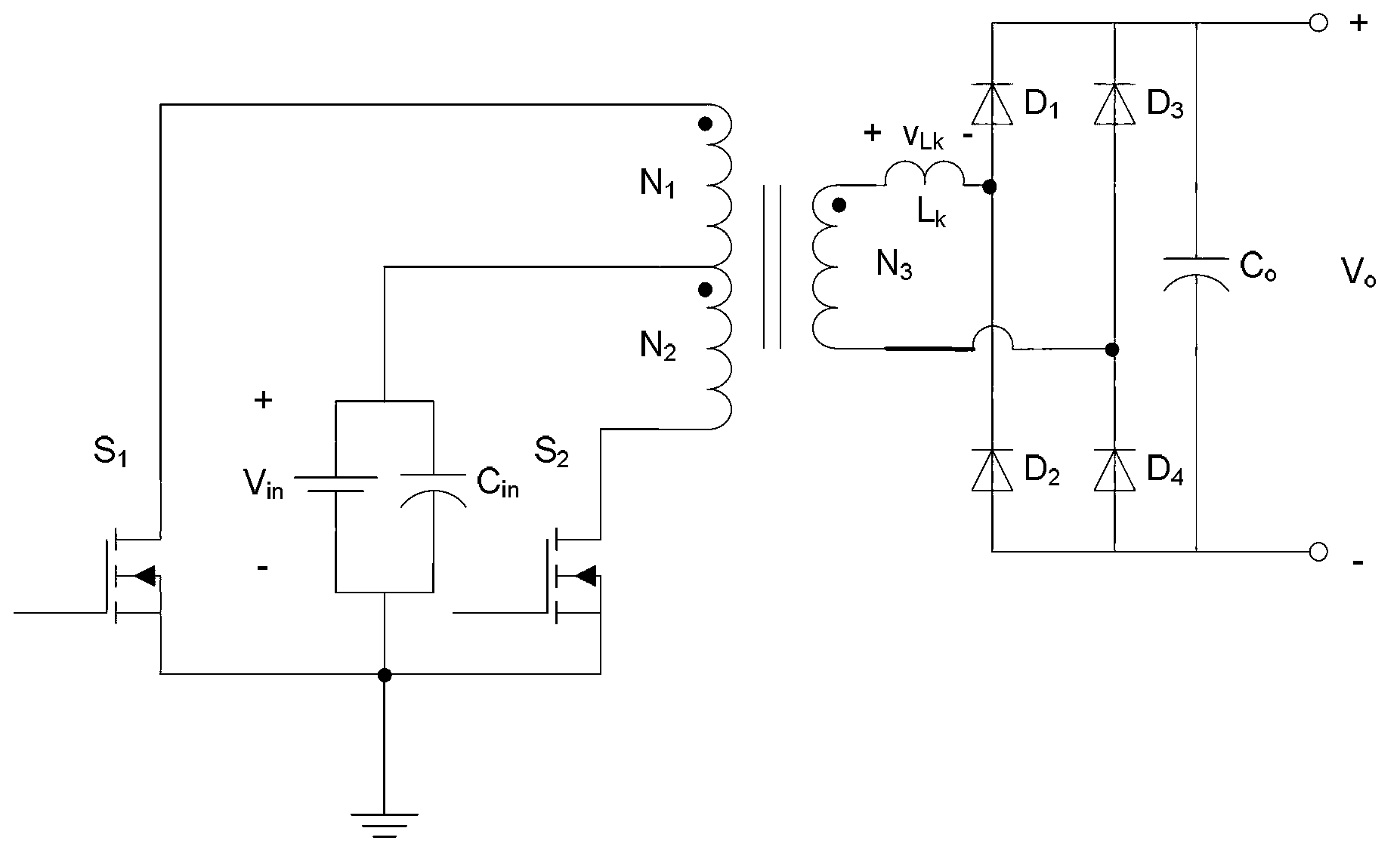
[0036] Such as Figure 4 As shown, a push-pull converter with voltage doubling resonance capability includes: primary side push-pull circuit, isolation transformer T, secondary side voltage doubling circuit and secondary side resonant circuit; where:

[0037] The primary side push-pull circuit is used to convert the DC input voltage V in (12V) is converted into an AC voltage; in this embodiment, it includes an electrolytic capacitor Cin and two NMOS transistors S 1 ~S 2 ; Among them, the electrolytic capacitor C in The positive pole of the isolation transformer T is connected to the middle tap point of the primary winding, and the electrolytic capacitor C in The negative pole of the NMOS tube S 1 The source and NMOS transistor ...


PUM


Abstract

The invention discloses a push-pull converter with voltage multiplying resonance capability. The push-pull converter comprises a primary side push-pull circuit, an isolation transformer, a secondary side voltage multiplying circuit and a secondary side resonance circuit. The push-pull converter has the advantages that on the basis of omitting the filter inductance, the secondary side utilizes the voltage multiplying structure, the gain of the converter is improved, the goal that the number of turns of the transformer is reduced to one half of the number of the original turns under the condition with the same voltage boosting ratio, and the size and the weight of the transformer are effectively reduced; in addition, a voltage multiplying capacitor also participates in the resonance of the secondary side equivalent leakage inductance of the transformer, the zero-current shutoff of a secondary side rectifier diode is realized, the reverse recovery problem of the rectifier diode is solved, the loss is reduced, and the integral efficiency of the converter is improved; and meanwhile, the primary side adopts the minimum element number, one capacitor and one group of transformer windings are reduced by the secondary side, miniaturization and light weight of the converter are realized, and in addition, the cost of the converter is reduced.

Description

technical field [0001] The invention belongs to the technical field of DC-DC (direct current-direct current) conversion, and in particular relates to a push-pull converter with voltage doubling resonance capability. Background technique [0002] The push-pull converter is one of the options in the boost converter. The push-pull transformer without inductance has obvious improvement in cost and volume, but because of its intermittent current, it is often used in circuits with low power levels. , such as the pre-stage DC boost circuit of the vehicle inverter. [0003] However, since this type of push-pull converter has no inductance element for energy storage, it cannot effectively adjust the energy balance to change the output voltage by controlling the duty cycle of the switch tube, and its voltage gain is almost realized by the transformer turn ratio. A higher turn ratio increases the volume of the transformer, increases the leakage inductance, and increases the loss, whic...

Claims


Application Information

Patent Timeline
Patent Type & Authority Applications(China)
IPC IPC(8): H02M3/337
CPCY02B70/1433Y02B70/1491Y02B70/10
Inventor 马皓陈隆宇王禹玺刘秦维
Owner ZHEJIANG UNIV
Why Eureka
Try Eureka