Coal-based direct reduced iron shaft furnace

A reduced iron, direct technology, applied in the field of shaft furnace, coal-based direct reduced iron shaft furnace, can solve the problems of uneven heating of pellets, low discharge efficiency, low degree of automation, etc., achieve oxidation resistance heat transfer effect, improve Yield, production efficiency, and effect of improving heat utilization

Active Publication Date: 2013-05-08
ZHENGZHOU ANLIANKAI IND CO LTD
View PDF4 Cites 15 Cited by
  • Summary
  • Abstract
  • Description
  • Claims
  • Application Information

AI Technical Summary

Problems solved by technology

Due to the large and short reduction chamber of the existing coal-based direct reduction iron shaft furnace, the small heating area of ​​the oxidized pellets in the tubular chamber, the uneven heating of the pellets, and the short residence time of the high-temperature gas heating the reduction chamber, the coal-based The direct reduced iron process has high energy consumption and low production capacity. At the same time, the existing shaft furnace discharge device is likely to cause secondary oxidation of high-temperature reduced pellets in contact with air during production. The shortcomings of low material efficiency and low degree of automation cannot meet the production requirements of reduced iron

Method used


Image

  • Coal-based direct reduced iron shaft furnace
  • Coal-based direct reduced iron shaft furnace
  • Coal-based direct reduced iron shaft furnace

Examples


Embodiment

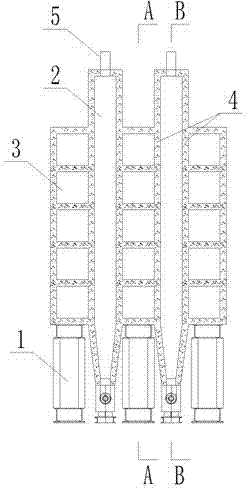
[0034] In the coal-based direct reduction iron shaft furnace of the present invention, the furnace body is integrally erected on the supporting steel structure 1, and the furnace body is provided with two reduction chambers 2 and three combustion chambers 3, the reduction chamber 2 and the combustion chamber 3 The heat conduction wall 4 is arranged at intervals to form a combustion chamber 3 on both sides of the reduction chamber 2, and a combustion chamber 3 is shared between the two reduction chambers 2 (such as figure 1 shown), the shown heat conduction wall 4 is made of high alumina bricks and silicon carbide bricks.

[0035] The upper part of the reduction chamber 2 is provided with a sealed feed port 5, the sealed feed port 5 is a high-temperature-resistant chute, and a pellet with a plug-in baffle structure is also arranged between the sealed feed port 5 and the reduction chamber 2. Cutting device (not shown in the figure), the inner top of the reduction chamber 2 is pr...


PUM


Abstract

The invention discloses a coal-based direct reduced iron shaft furnace and belongs to the technical field of coal-based direct reduced iron process equipment. The furnace body of the coal-based direct reduced iron shaft furnace is erected at a support steel structure, and the furnace body comprises a reduction cavity, burning cavities, and a discharge device; the reduction cavity is a rectangular structure cavity body composed of two parallel heat-conduction walls and the upper and lower parts of the reduction cavity are respectively provided with a sealed feed port and a sealed discharge port; the burning cavities provided with multiple layers of horizontal fire gas baffling channels are positioned at the both sides of the reduction cavity; and the discharge device is a spiral conveyer, the cylindrical shell of the spiral conveyer is of a jacket water cooling structure, and a spiral rotating shaft is a hollow water cooling structure. Compared with the tradition tubular reduction cavity body, the coal-based direct reduced iron shaft furnace provided by the invention has the advantages of high efficiency of heat transmission, and uniform heating of the inner and outer layers of a pelletized material in the furnace. The coal-based direct reduced iron shaft furnace can be used for effectively reducing the energy consumption of reduced iron and improving the merchantable quality and the production efficiency of a single furnace.

Description

technical field [0001] The invention relates to a shaft furnace, in particular to a coal-based direct reduced iron shaft furnace, belonging to the technical field of coal-based direct reduced iron process equipment. Background technique [0002] Compared with the gas-based direct reduction process, coal-based direct reduction refers to a process that directly uses coal as a reducing agent. In the existing shaft furnace technology of coal-based direct reduced iron process, the oxidized pellets are heated and reduced in the tubular reduction chamber in the furnace, and then directly discharged from the bottom of the furnace through the discharge device to the conveying equipment and sent for cooling , slag iron separation or sent to the smelting process for further processing. The existing coal-based direct reduction iron shaft furnace structure is large and short due to the reduction chamber, the heating area of ​​the oxidized pellets in the tubular chamber is small, the pel...

Claims


Application Information

Patent Timeline
Patent Type & Authority Applications(China)
IPC IPC(8): C21B13/02
Inventor 陈谦
Owner ZHENGZHOU ANLIANKAI IND CO LTD
Why Eureka
Try Eureka