Supercharge Your Innovation With Domain-Expert AI Agents!

Exterior convex interior random tooth difference cam sleeve transmission internal-combustion engine

A cam sleeve, internal combustion engine technology, applied in the direction of machine/engine, mechanical equipment, etc., can solve the problems of shortening the life of the internal combustion engine, large unbalanced centrifugal force, large mechanical wear, etc., to improve the energy conversion efficiency, reduce the axial size, large The effect of the gear ratio

Inactive Publication Date: 2013-05-08
SICHUAN UNIV
View PDF10 Cites 0 Cited by
  • Summary
  • Abstract
  • Description
  • Claims
  • Application Information

AI Technical Summary

Problems solved by technology

Since this kind of internal combustion engine relies on the linear motion of the piston and the plane motion of the connecting rod to press and drive the crankshaft to rotate, there is a large friction between the motion pairs, resulting in low transmission efficiency of the internal combustion engine.
These existing crankshaft connecting rod type internal combustion engines also have the following main disadvantages: large volume; the unbalanced centrifugal force on the connecting rod and the crankshaft is relatively large; the impact is large and the vibration is large; and thus cause large mechanical wear and shorten the life of the internal combustion engine; The structure is complex, and processing, manufacturing, and assembly are relatively difficult; in addition, the internal combustion engine and the transmission device are usually two independent machines, and the internal combustion engine needs to be installed with a transmission for subsequent transmission, resulting in a large volume

Method used


Image

  • Exterior convex interior random tooth difference cam sleeve transmission internal-combustion engine
  • Exterior convex interior random tooth difference cam sleeve transmission internal-combustion engine

Examples


Embodiment Construction

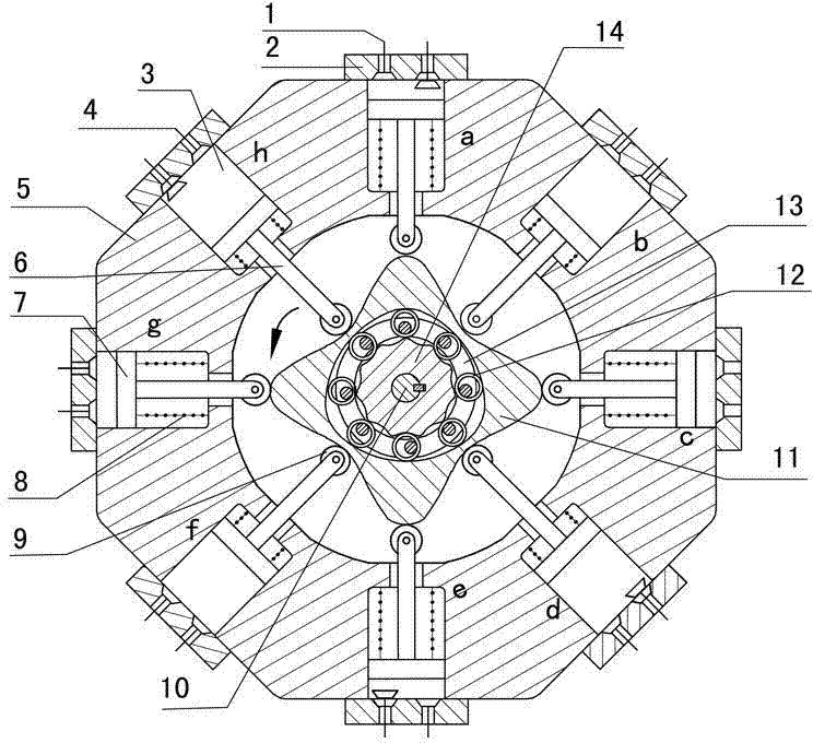
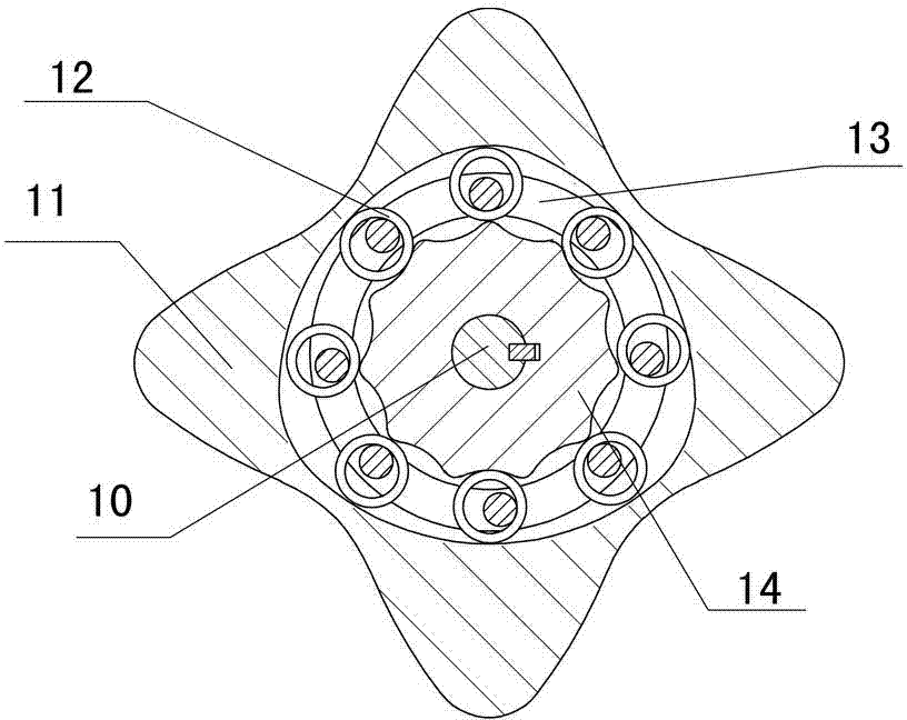
[0037] figure 1 , figure 2 The internal combustion engine is driven by the cam sleeve with any tooth difference between the convex inside and outside, and consists of exhaust valve (1), cylinder head (2), cylinder (3), intake valve (4), cylinder block (5), and piston (6) , push rod (7), spring (8), roller (9), output shaft (10), multi-phase inner cam (11), sleeve movable tooth (12), pin frame (13), Center wheel (14) etc. are formed. Eight air cylinders (3) are evenly and symmetrically distributed in a circular shape around the outer convex inner multiphase inner cam (11), and the angle between two adjacent air cylinders is 45°. There is a piston (6) in each cylinder (3), and one end of the push rod (7) is fixedly connected with the piston (6), and the other end is equipped with a roller (9), and the roller (9) makes the push rod ( 7) and the external convex internal multi-phase internal cam (11) are connected by rolling friction, one end of the spring (8) is fixed on the b...


PUM


Abstract

The invention discloses an exterior convex interior random tooth difference cam sleeve transmission internal-combustion engine, relates to the field of gas motive power, and belongs to multi-cylinder internal-combustion engines. The invention provides a novel internal-combustion engine. Eight air cylinders are annularly, symmetrically and evenly arranged around an exterior convex interior multiphase inner cam, the exterior convex interior multiphase inner cam is enabled to be stressed with zero resultant force. Pistons of the air cylinders are directly acted on the exterior convex interior multiphase inner cam through push rods. Motive power is transmitted to an output shaft which is in key joint with a center wheel through the exterior convex interior multiphase inner cam and random tooth difference interior cam sleeve oscillating tooth transmission. According to the internal-combustion engine, a connecting rod and a crank shaft of a traditional internal-combustion engine are removed, and an exterior convex interior multiphase inner cam sleeve transmission mechanism of the internal-combustion engine has the advantages of having no eccentric mass, having inertia force and being self-balanced in working load. Output shaft rotating speed depends on transmission ratio of oscillating tooth transmission. If pin frames are fixed, low velocity and large torque can be output through the center wheel. The internal-combustion engine can be widely applied to engineering machinery, armored cars and other devices needing high power, and is simple and compact in structure, small in axial dimension, self-balancing in stress and stable in operation.

Description

technical field [0001] The invention relates to the field of gas power, more specifically, an internal combustion engine driven by a cam sleeve with an outer convex inner arbitrary tooth difference. Background technique [0002] At present, a general internal combustion engine (engine) is composed of a body, a crank connecting rod mechanism, a gas distribution mechanism, a cooling system, a lubrication system, a fuel system, and an ignition system. stroke. The transmission mechanism of this type of internal combustion engine uses a crank-connecting rod mechanism, which transmits the power of the piston to the crankshaft through the connecting rod, and converts the reciprocating linear motion of the piston into the rotary motion of the crankshaft. Because this internal combustion engine presses and drives the crankshaft to rotate by the linear motion of the piston and the planar motion of the connecting rod, there is greater friction between the kinematic pairs, resulting in...

Claims


Application Information

Patent Timeline
IPC IPC(8): F02B75/32
Inventor 梁尚明贺飞飞黎磊
Owner SICHUAN UNIV
Features
  • R&D
  • Intellectual Property
  • Life Sciences
  • Materials
  • Tech Scout
  • Unparalleled Data Quality
  • Higher Quality Content
  • 60% Fewer Hallucinations
Learn More