Mechanical-thermal composite in-situ loading system

A thermal compounding and in-situ loading technology, which is applied in the direction of applying stable tension/pressure to test the strength of materials, can solve problems such as transverse cracks, film debonding and structural failure, and achieve uniform heating, simple and reliable loading methods, and high performance. The effect of measurement accuracy

Inactive Publication Date: 2013-05-08
TIANJIN UNIV
View PDF4 Cites 16 Cited by
  • Summary
  • Abstract
  • Description
  • Claims
  • Application Information

AI Technical Summary

Problems solved by technology

When subjected to thermal cycle load at the same time, the original buckling will produce transverse cracks, which can easily lead to large-area debonding of the film and failure of the structure

Method used


Image

  • Mechanical-thermal composite in-situ loading system
  • Mechanical-thermal composite in-situ loading system
  • Mechanical-thermal composite in-situ loading system

Examples


Embodiment 1

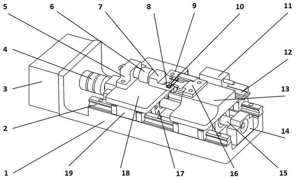
[0019] use figure 1 The setup shown is an example of an experiment with a 150 nm thick aluminum film deposited on a plexiglass substrate. Base material size: length 8mm, width 5mm, height 3mm, observed with 1000 times optical microscope. Pic 4-1 It is the buckling topography of the film surface under the condition of the sample at room temperature and the compressive load of 160N, Figure 4-2 It is the buckling morphology diagram of the sample after the compressive load is gradually increased to 200N, and it has undergone 10 times of thermal cycle loading from room temperature 27°C to 37°C. From Pic 4-1 , 4-2 It can be seen from the two experimental images that the observation area in the field of view of the film substrate structure does not move out of the field of view of the microscope under compressive load and thermal cycle load. It shows that the device can effectively realize in-situ observation. In the process of increasing load and thermal cycle loading, the b...


PUM


Abstract

The invention discloses a mechanical-thermal composite in-situ loading system which comprises a stepping motor connected with the base, wherein a motor shaft of the stepping motor is connected with a bidirectional ball screw through a coupler; a left lead screw nut and a right lead screw nut are in threaded connection on the bidirectional ball screw; a left objective table and a right objective table are respectively arranged on the left lead screw nut and the right lead screw nut; a left end support and a left clamp are fixedly connected to the left objective table; one end of the base is fixedly connected with the left objective table and the other end of the base is freely suspended; a force sensor is arranged between the left end support and the left clamp; an electric heating film is fixed on the left clamp; a right clamp is fixedly connected to the right objective table; a grating ruler reading head of a grating ruler displacement sensor is fixed on the one side face of the right objective table; a grating ruler main body of the grating ruler displacement sensor is adhered to the base; and the right clamp can press a test piece which is arranged on the electric heating film of the left clamp. The in-situ loading of submicron scale can be realized.

Description

technical field [0001] The invention relates to nanometer thin film material performance testing equipment, in particular to a nanometer thin film force-thermal composite in-situ loading system suitable for deposition on a substrate. Background technique [0002] Materials are the material basis for human survival and development. The study of materials is of great significance to national economic construction, national defense construction, and people's lives, and is generally valued at home and abroad. With the rise of nanoscience and technology in recent years, nano-functional composite materials and thin-film materials deposited with nano-scale coatings have rapidly become the focus of attention. Microelectromechanical systems are one of the key areas for the application of nanometer thin film materials. [0003] Micro-Electro-Mechanical Systems MEMS (Micro-Electro-Mechanical Systems) is a high-tech cutting-edge discipline developed on the basis of integrating various...

Claims


Application Information

Patent Timeline
Patent Type & Authority Applications(China)
IPC IPC(8): G01N3/18
Inventor 何巍王世斌李林安张冠华薛秀丽贾海坤郭志明
Owner TIANJIN UNIV
Why Eureka
Try Eureka