
Residual oil hydrogenation method for high quality diesel oil yield increase

A technology for residual oil hydrogenation and diesel oil, which is applied in the fields of hydrotreating process, petroleum industry, and hydrocarbon oil treatment, etc. It can solve the problems of shortening the operation period of carbon deposits in the bed, stopping the operation to replace the catalyst, and increasing the hydrogen consumption, etc.

Active Publication Date: 2013-05-15
CHINA PETROLEUM & CHEM CORP +1
View PDF17 Cites 2 Cited by
  • Summary
  • Abstract
  • Description
  • Claims
  • Application Information

AI Technical Summary

Problems solved by technology

But the H generated during the production process 2 O has an adverse effect on the residue hydrogenation catalyst, and the reaction produces CO and CO 2 It will affect the performance of the catalyst, and the methanation reaction will occur, and the generated methane is difficult to discharge from the system, thereby greatly reducing the hydrogen partial pressure of the reaction system, or discharging methane through the discharge method, which greatly increases the hydrogen consumption of the device
[0007] In the bio-oil hydrogenation process including the above method, one of the main problems encountered is that the carbon deposition in the bed causes the shortening of the operation cycle, and frequent shutdowns are required to replace the catalyst, especially when the bio-oil is used as a raw material alone or the mixing ratio of bio-oil is high. , the operating cycle of the hydrogenation catalyst is more significantly affected
For the hydrogenation unit for blending bio-oil, the H produced in the reaction process 2 O, CO, and CO 2 and CH 4 etc. will have a very adverse effect on the existing hydrogenation catalyst system

Method used


Image

  • Residual oil hydrogenation method for high quality diesel oil yield increase

Examples


Embodiment Construction

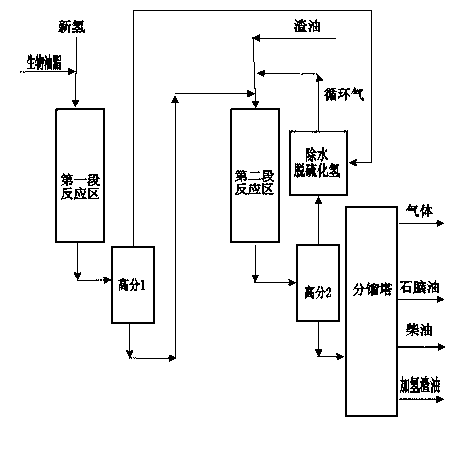
[0023] The method of the present invention is specifically as follows: one or several mixed oils and new hydrogen in the bio-grease pass through the first-stage hydrogenation reaction zone comprising at least two hydrogenation catalysts under hydrogenation operation conditions, and the obtained hydrogenation generates The gas separated from the oil in the high-pressure separator (referred to as high fraction) is mixed with the gas phase of the reaction product in the second-stage reaction zone for dehydration and dehydrogen sulfide treatment, and then used in the second-stage reaction zone. The obtained liquid fraction is mixed with residual oil and The circulating hydrogen is mixed into the second-stage reaction zone containing a series of residual oil hydrogenation catalysts, and the hydrogenated stream is separated in the high-pressure separator (abbreviated as high fraction), and the gas obtained is recycled in the second stage, and the obtained liquid is fractionated to obt...


PUM


Abstract

The present invention relates to a residual oil hydrogenation method for high quality diesel oil yield increase. According to the method, under a hydrogenation condition, a biological oil and new hydrogen are mixed, and pass through a first stage hydrogenation reaction zone, the stream generated from hydrogenation is separated to obtain hydrogen-rich gas, the hydrogen-rich gas is adopted as second stage supply hydrogen to be used, the separated liquid and the residual oil are mixed and enter a second stage residual oil hydrogenation reaction zone, the sub-hydrogen gas separated from the oil generated through second stage hydrogenation is recycled at the second stage, and the separated liquid product is subjected to fractionation to obtain naphtha, high quality diesel oil and hydrogenation residual oil, wherein hydrogenation activity components of the hydrogenation catalyst used at the first stage are one or a plurality of materials selected from reduction state W, Mo, Ni and Co under a reaction state. Compared to the method in the prior art, the residual oil hydrogenation method of the present invention has the following characteristics that: the high quality diesel oil can be by-produced on the residual oil hydrogenation device, activity stability of the catalyst is good, and the device can stably operate for a long period.

Description

technical field [0001] The invention relates to a hydrogenation method, in particular to a residual oil hydrogenation method capable of producing more high-quality diesel oil. Background technique [0002] At present, the energy on a global scale mainly comes from fossil energy, among which petroleum is the most important source of motor fuel. Petroleum is a non-renewable energy source. Not only are the resources increasingly depleted, but also the trend of heavy and inferior quality is intensifying. The continuous development of the world economy and increasingly stringent environmental protection regulations require the production of a large amount of light and clean fuels, which require the improvement of the existing refining technology. Add new oil substitutes while improving, and produce products that meet the requirements at the lowest cost. For the conversion of residual oil, there are mainly two ways: hydrogenation of residual oil and coking. Among them, hydrogenat...

Claims


Application Information

Patent Timeline
IPC IPC(8): C10G67/02C10G3/00
CPCY02P30/20
Inventor 李洪广吴锐张晔蒋立敬刘铁斌翁延博张庆军韩照明
Owner CHINA PETROLEUM & CHEM CORP
Learn More