Measurement testing device of external characteristics and internal flow of fused salt model pump
A test device and internal flow technology, which is applied to components, pumps, and pump control of pumping devices for elastic fluids, and can solve problems such as inability to measure, single function, and unreasonable design of model pumps for testing, etc.
- Summary
- Abstract
- Description
- Claims
- Application Information
AI Technical Summary
Problems solved by technology
Method used
Image
Examples
Embodiment 1
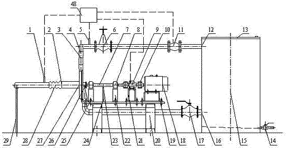
[0067] The test device for measuring the external characteristics and internal flow of the molten salt model pump includes 5 main parts: pipeline system, power transmission system, model pump, external characteristic data acquisition and analysis system, and internal flow measurement system. The test device has three functions: measurement of the external characteristics of the model pump, PIV measurement of the internal velocity field of the model pump, and high-speed imaging measurement of the internal flow of the model pump, which can realize the experimental research on the external characteristics of the pump and the internal full flow field.
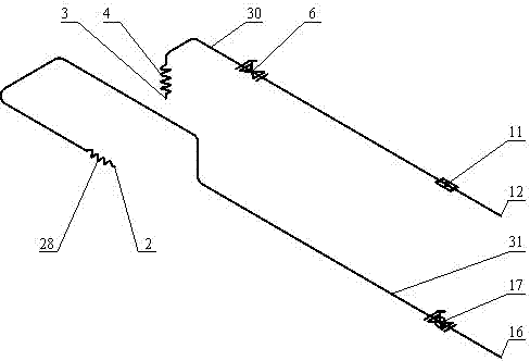
[0068] exist figure 1 Among them, the pipeline system of the present invention is composed of a storage tank (15), a ball valve (17), a pump inlet hose (28), a pump outlet hose (4), a regulating valve (6) and corresponding connecting pipelines. All flow parts except hoses are made of stainless steel to prevent rust from polluting ...
Embodiment 2
[0078] The main steps of external characteristic measurement are:
[0079] 1) Remove the sundries in the storage tank (15), and fill the test medium into the storage tank to an appropriate level.
[0080] 2) Check whether the equipment is normal.
[0081] 3) Separate the torque speed sensor (9) from the transmission shaft (7), adjust the motor (18) to the test speed through the frequency converter, and then zero-adjust the torque speed sensor (9).
[0082] 4) Connect the motor (18) to the transmission shaft (7), remove the impeller (41) in the pump, adjust the frequency converter to adjust the motor to the test speed, and record the no-load torque of the model pump.
[0083] 5) Open the ball valve (17) to prime the pump.
[0084] 6) Turn on the power supply of each instrument, the instrument switch is in the "OFF" position, press the motor start button, and start the model pump (27). Adjust the frequency converter so that the speed gradually increases from small to large ...
Embodiment 3
[0094] The main steps of the PIV measurement of the pump internal velocity field are:
[0095] 1) Arrange the PIV measurement system.
[0096] When measuring the velocity field inside the impeller channel and pressurized water chamber, the layout of the PIV system is as follows: Figure 5 shown. The trigger signal sent by the Hall sensor (23) controls the CCD camera (49) and the laser (50) simultaneously through the synchronous controller (47), and the CCD camera (49) transmits the pictures taken to the computer unit (48). The thickness of the sheet light emitted by the laser (50) is controlled within 1mm, and the interior of the model pump is irradiated from the side of the volute (37), and the CCD camera (49) is facing the area illuminated by the laser sheet light, keeping an appropriate distance from the laser sheet light ( about 500 mm), adjust the focus until the image is clear. Because the blade is a binary blade, the main flow surface in the impeller is parallel to...
PUM
 Abstract
Description
Claims
Application Information
 - R&D
- Intellectual Property
- Life Sciences
- Materials
- Tech Scout
- Unparalleled Data Quality
- Higher Quality Content
- 60% Fewer Hallucinations
Browse by: Latest US Patents, China's latest patents, Technical Efficacy Thesaurus, Application Domain, Technology Topic, Popular Technical Reports.
© 2025 PatSnap. All rights reserved.Legal|Privacy policy|Modern Slavery Act Transparency Statement|Sitemap|About US| Contact US: help@patsnap.com


