Machining method of injection molding face gear electrode and injection molding face gear

A processing method and technology of face gears, applied in electric processing equipment, electrode manufacturing, components with teeth, etc., can solve the problems of low precision of face gears, expensive equipment, complicated process, etc., and achieve low transmission noise and low cost , the effect of accurate data

Active Publication Date: 2013-06-05
SHENZHEN ZHAOWEI MACHINERY&ELECTRONICS CO LTD
View PDF10 Cites 11 Cited by
  • Summary
  • Abstract
  • Description
  • Claims
  • Application Information

AI Technical Summary

Problems solved by technology

As for the processing technology of face gears, face gears can be processed by shaping, hobbing and grinding, but only a few technical materials or related patents disclose the methods of shaping and hobbing in China. For example, the Chinese patent application number is 201110053078.6, the name is a face gear CNC hobbing processing control device and processing control method, and the Chinese patent application number is 201010269920.5, the name is a face gear hobbing processing equipment, all of which are processed by hobbing. To process face gears, only Zhu Rupeng's team from Nanjing University of Aeronautics and Astronautics has conducted preliminary research on the gear shaping technology and grinding principles of face gears. Processing, the precision of the processed face gear is very low, and the practicability is not strong
[0004] Whether it is gear shaping or hobbing, it is necessary to use special software to drive the face gear forming tool during processing, and each modulus of face gear must correspond to a forming tool, so purchase these special software and forming tools The cost of processing the face gear is high. On the other hand, due to the pressure of the forming tool on the face gear blank, the face gear will be slightly deformed, resulting in low precision of the processed face gear. If the precision and hardness of the face gear are to be improved, it is necessary to For gear grinding, the process is complicated and the equipment is more expensive

Method used


Image

  • Machining method of injection molding face gear electrode and injection molding face gear
  • Machining method of injection molding face gear electrode and injection molding face gear
  • Machining method of injection molding face gear electrode and injection molding face gear

Examples


Embodiment 1

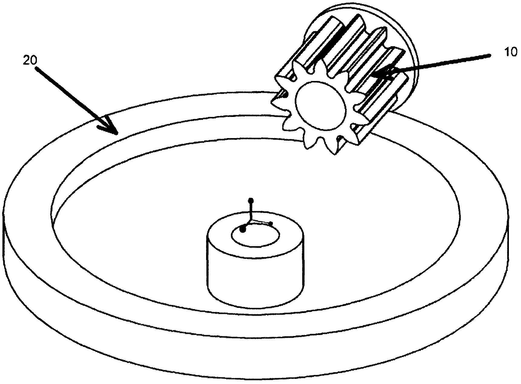
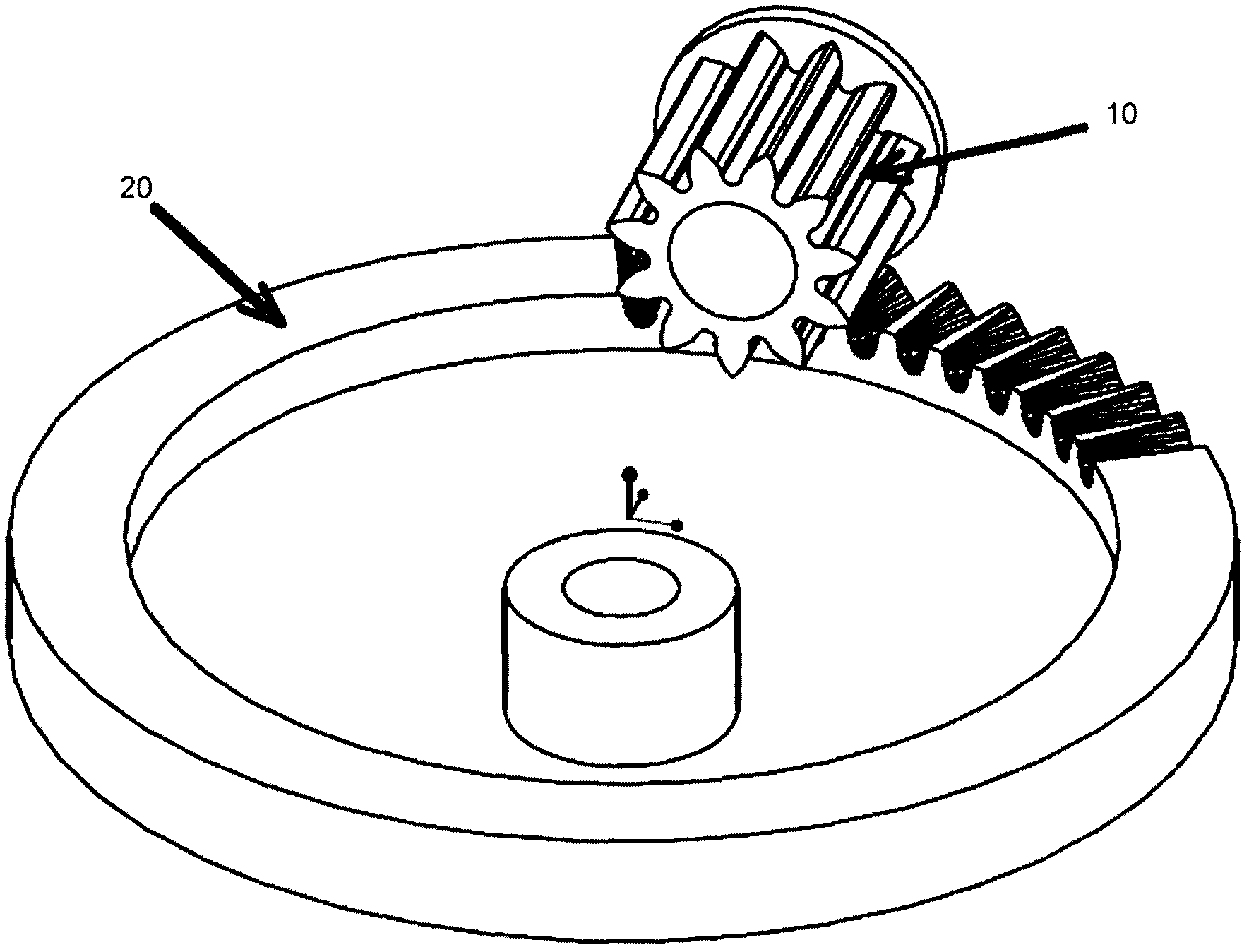
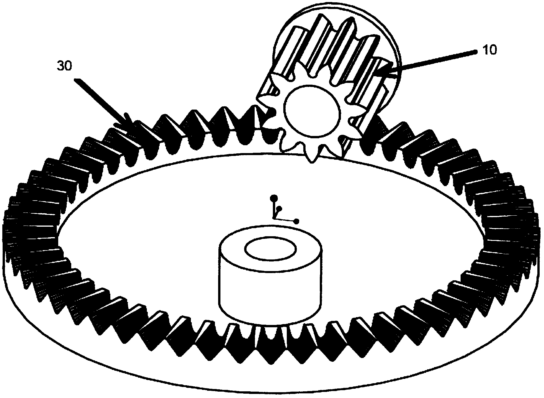
[0037] This embodiment provides a method for processing an injection-molded surface gear electrode. The surface gear referred to in the present invention means that all the gear teeth are on the same disc surface. In fact, when we process an injection-molded surface gear electrode, we know that the surface The outer diameter of the gear, the inner diameter of the face gear, but the tooth shape data of the face gear is unknown, so the tooth shape data of the face gear we want to generate. At the same time, before processing the required face gear, we know the relative position of the face gear and the cylindrical gear driven by the face gear, and the cross-sectional diameter of the cylindrical gear driven by the face gear, the number of teeth of the cylindrical gear, and the We can also know the data of tooth pitch and tooth depth of cylindrical gear. So, if Figure 1-3 As shown, the processing method of the injection surface gear electrode is as follows:

[0038] S1. Constru...

Embodiment 2

[0044] The difference between this embodiment and Embodiment 1 is that the teeth of the face gear are not on the same disc surface, the face gear is actually a bevel gear, the rotation center axis of the bevel gear and the center The included angle of the shaft is less than 90°, the processing method of the gear electrode on the injection surface is the same as the other steps in Example 1, the difference is:

[0045] S2. In the UG software, a conical wheel blank is constructed according to the inner diameter of the actual face gear tooth disc, the outer diameter of the face gear tooth disc, and the central axis of the face gear and the angle with the central axis of the cylindrical gear driven by the face gear. For example: build a bevel gear with an inner diameter of 10cm and an outer diameter of 11cm, the central axis of the face gear and the central axis of the cylindrical gear driven by the face gear at an angle of 60°.

Embodiment 3

[0047] The processing steps of this embodiment are the same as those of Embodiment 1. The difference is that the tooth depth of the face gear is different from that of the cylindrical gear. The tooth depth of the cylindrical gear is 1.5 cm, while the tooth depth of the face gear is 1 cm. Therefore Set the distance between the central axis of the cylindrical gear and the disc surface of the face gear to be 4cm, then the distance between the central axis of the cylindrical gear and the disc surface of the face gear will be larger than that in Example 1, so adjust the relative positions of the cylindrical gear and the face gear Different face gear tooth depths can be generated. When the face gear and the spur gear are driving, the teeth of the face gear are not completely inserted into the tooth grooves of the spur gear, while the teeth of the spur gear are completely inserted into the tooth grooves of the face gear.


PUM

PropertyMeasurementUnit
angleaaaaaaaaaa

Abstract

The invention provides a machining method of an injection molding face gear electrode and an injection molding face gear. A face gear transmission principle is used, a three-dimensional vector diagram of the face gear is generated in a generating method through computer-assisted software, then the injection molding face gear electrode is machined through a numerical control lathe, a mold cavity of the face gear is machined in an electric spark discharge technology, and accordingly the face gear is formed by infection molding. Due to the fact that transmission data of the face gear and a cylinder gear is simulated in a computer, the machined infection molding face gear completely meets face gear transmission requirements in practice, data is accurate, the face gear is fixed on a table face to be machined through the numerical control lathe, deformation cannot happen, and therefore the machined injection molding face gear electrode is high in accuracy and low in transmission noise. What is important is that technologies such as gear inserting or gear rolling or gear grinding are not used in machining of the injection molding face gear electrode, so that special knives are of no need, and cost is greatly lowered.

Description

【Technical field】 [0001] The invention relates to a processing method of an electrode of an injection-molding surface gear and an injection-molding surface gear, in particular to a three-dimensional image of an electrode of an injection-molding surface gear processed by a generating method, and then the electrode of the injection-molding surface gear is processed by a numerical control machine tool, and the processed injection molding The method of injecting the face gear electrode into the gear cavity through electric discharge machining, and then injecting the face gear. 【Background technique】 [0002] Face gear transmission is a gear transmission in which a cylindrical gear meshes with a face gear. When the teeth of the face gear are distributed on a circular plane, the bevel gear is the face gear, so it is generally called the face gear transmission. The tooth surface geometry of the face gear is no longer the common involute tooth surface or other common tooth surfaces...

Claims


Application Information

Patent Timeline
Patent Type & Authority Applications(China)
IPC IPC(8): B23H1/04G06F17/50B23F13/00B23H9/00
Inventor 李海周徐尚祥
Owner SHENZHEN ZHAOWEI MACHINERY&ELECTRONICS CO LTD
Why Eureka
Try Eureka