Roasting shaft furnace

A shaft furnace and roasting technology, applied in the field of mineral roasting equipment, can solve the problems of low furnace operation rate, loss of cooling beam wall effect, short maintenance cycle, etc., to reduce investment and maintenance costs, reduce oil resource consumption, and increase operations. The effect of rate and yield

Active Publication Date: 2013-06-05
ZHONGYE-CHANGTIAN INT ENG CO LTD
View PDF8 Cites 1 Cited by
  • Summary
  • Abstract
  • Description
  • Claims
  • Application Information

AI Technical Summary

Problems solved by technology

[0006] 1) The service life of the central air guide wall 2 is extremely short: due to the constraints of the large water beam 3 and the wall, the central air guide wall 2 has an extremely short service life, the longest is more than a year, and the shortest is dozens of days, and it is extremely troublesome to repair and replace , once the central wind guide wall 2 collapses, it will take a long time to repair, seriously affecting production, and at the same time, the maintenance intensity of workers and the environment are quite bad
[0007] 2) With the central air guide wall 2, the shaft furnace needs to be equipped with large-scale cooling equipment adapted to it, which brings a series of problems such as high equipment maintenance costs, short maintenance cycles, low furnace operation rate, and high furnace investment costs
[0008] 3) The length of the large water beam 3 should not be too long, otherwise the internal water temperature will be too high and the effect of cooling the beam wall will be lost
However, the restriction on the length of the large water beam 3 indirectly led to the inability to enlarge the size of the traditional shaft furnace, which brought losses to the iron and steel enterprises.
[0009] 4) Because the shaft furnace only relies on the combustion chambers 4 on both sides for heat supply, the temperature cannot be adjusted and evenly distributed in four stages, which will easily cause nodules in the downward process of the pellets, resulting in the frequent need to stop the furnace to clean the kiln, which is harmful to the steel plant The manpower and material resources have caused a great burden, but also seriously affected the annual operation rate and annual output

Method used


Image

  • Roasting shaft furnace
  • Roasting shaft furnace
  • Roasting shaft furnace

Examples


Embodiment Construction

[0037] The present invention will be further described in detail below in conjunction with the accompanying drawings and specific embodiments.

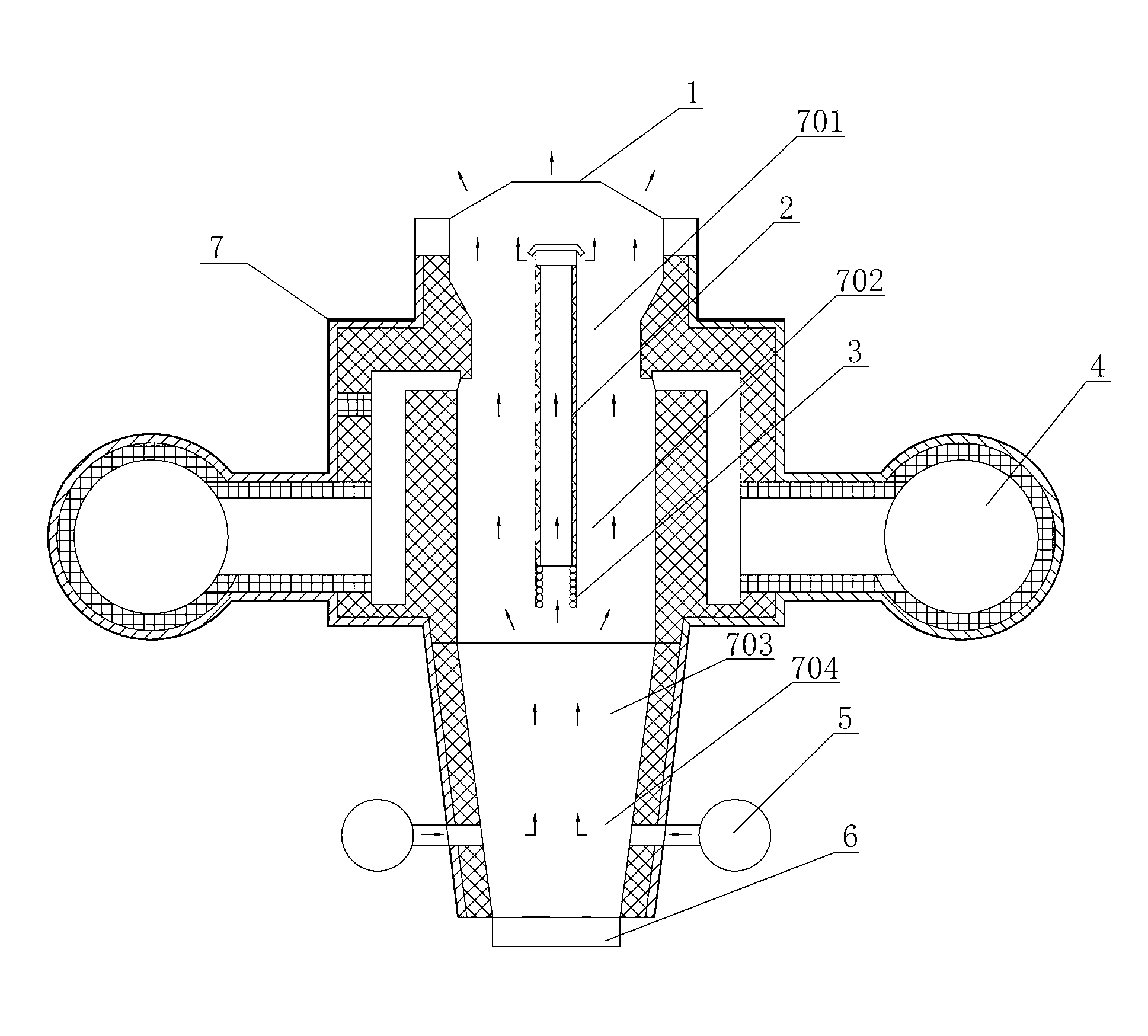
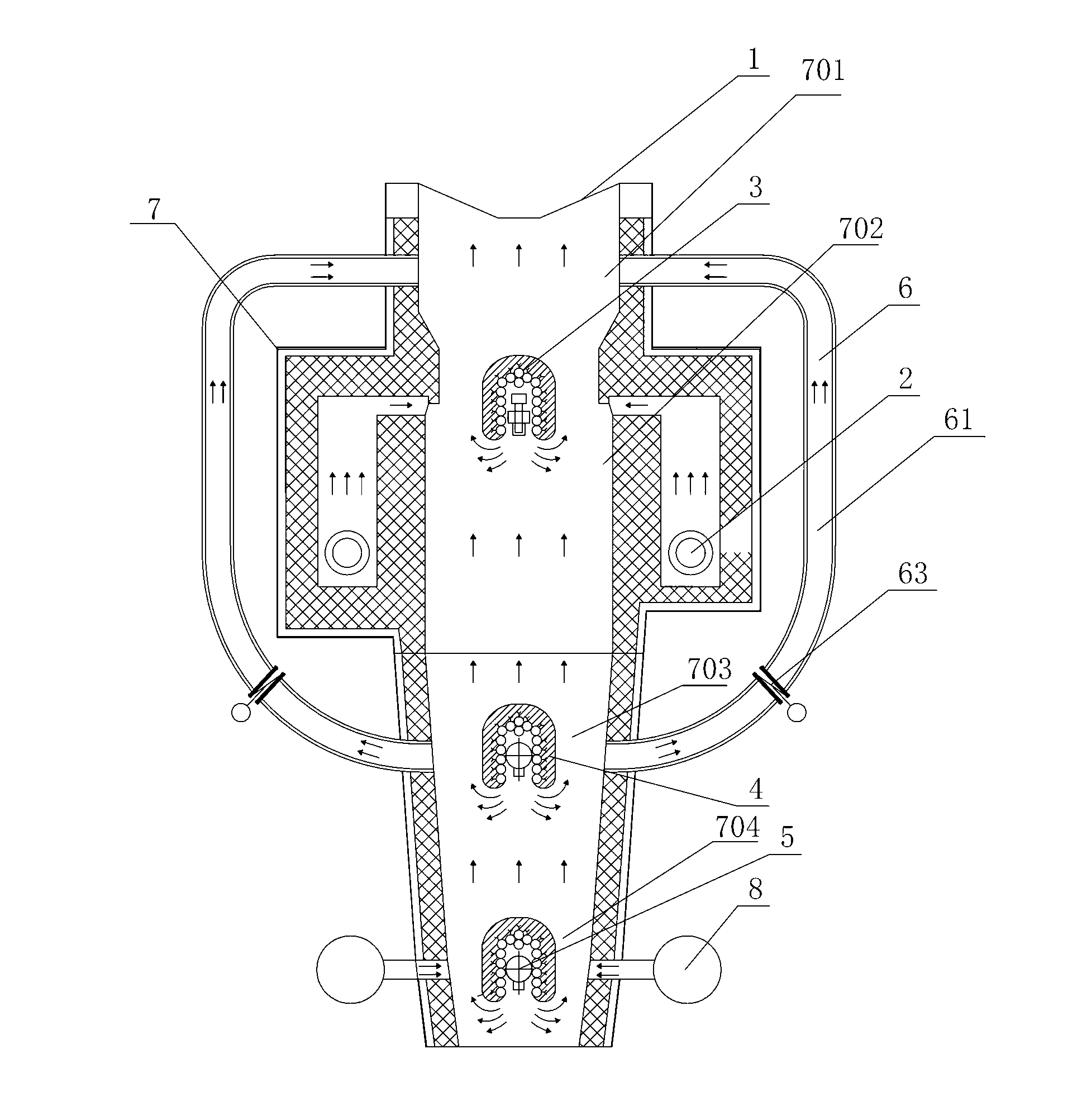
[0038] Such as figure 2 As shown, the roasting shaft furnace of the present invention includes a furnace body 7, more than two combustion chambers 4 and a drying bed 1 positioned at the top of the furnace body 7, and the inner chamber of the furnace body 7 is divided into drying sections 701 from top to bottom. , roasting section 702, soaking section 703 and cooling section 704 (various airflows in the furnace run in the direction of the arrow in the figure), the combustion chamber 4 is located at the position corresponding to the side of the furnace body 7 and the roasting section 702 and communicates with the furnace cavity. The furnace body 7 is provided with a return hot air assembly 6, the air inlet end of the return hot air assembly 6 communicates with the furnace inner cavity located at the bottom of the combustion chamber 4, ...


PUM


Abstract

The invention discloses a roasting shaft furnace which comprises a furnace body, more than two combustion chambers and a drying bed located at the top of the furnace body. An inner cavity of the furnace body is sequentially divided into a drying section, a roasting section, a soaking section and a cooling section from top to bottom. The combustion chambers are located at the position, corresponding to the roasting section, of the lateral side of the furnace body and communicated with the inner cavity of the furnace body. A hot air return assembly is arranged on the furnace body. An air inlet end of the hot air return assembly is communicated with the position, located at the bottoms of the combustion chambers, of the inner cavity of the furnace body. An air outlet end of the hot air return assembly is communicated with the position, located between the tops of the combustion chambers and the drying bed, of the inner cavity of the furnace body. The roasting shaft furnace has the advantages of being simple and compact in structure, low in cost, long in service life, stable and reliable in working, strong in operational adjustment, capable of optimizing furnace inside atmosphere and reducing energy consumption for material roasting, even in heating and the like.

Description

technical field [0001] The invention mainly relates to the field of mineral roasting equipment, in particular to a shaft furnace for roasting. Background technique [0002] Shaft furnaces are widely used in the field of oxidative roasting of iron ore pellets or direct reduction of iron. In the iron and steel metallurgy industry, they are used for oxidative roasting of iron ore pellets or direct reduction of pellets to iron. They are indispensable process equipment in iron and steel metallurgy; At the same time, it can also be used for the roasting of massive materials such as limestone and dolomite to produce lime, which is a very common roasting equipment. As a kind of roasting equipment, the shaft furnace has the advantages of small footprint, less process, and overall investment saving compared with the rotary kiln, and has high promotion value for small and medium-sized steel plants. [0003] Common shaft furnace structures such as figure 1 As shown: the materials are ...

Claims


Application Information

Patent Timeline
Patent Type & Authority Applications(China)
IPC IPC(8): F27B1/06F27B1/10F27B1/14F27B1/16F27B1/24
Inventor 贺新华周浩宇
Owner ZHONGYE-CHANGTIAN INT ENG CO LTD
Why Eureka
Try Eureka