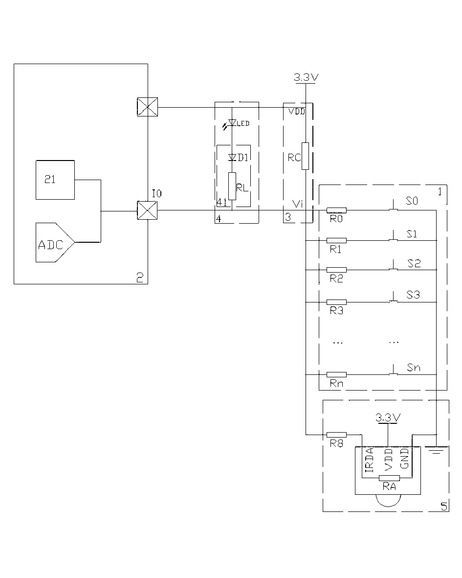
[0034] like figure 1 As shown, this embodiment provides a key detection circuit integrating LED driving and infrared remote control receiving functions. The circuit includes a button resistor network 1 and an MCU chip 2, the button detection circuit also includes a shared pull-up resistor 3, an LED drive circuit 4 and an infrared remote control receiving circuit 5, one end of the shared pull-up resistor 3 is connected to a power supply, and the other end is connected to a power supply. The button resistor network 1 is connected in series to a common ground, the LED drive circuit 4 is connected in parallel with the shared pull-up resistor 3, and the node connected between the shared pull-up resistor 3 and the button resistor network 1 is connected to the MCU chip 2 One of the pins is connected, and the infrared remote control receiving circuit 5 is connected in parallel with the button resistor network 1. The parallel circuit formed by the LED drive circuit 4 and the shared pull-up resistor 3 and the parallel circuit formed by the infrared remote control receiving circuit 5 and the button resistance network 1 are connected in series, and Vi is set to be between the two parallel circuits. The node voltage of Vi is connected with the pin of the MCU chip.
[0035] The LED driving circuit 4 is composed of a current limiter 41 and an LED in series, and the current limiter 41 is composed of a current limiting resistor or a current limiting resistor and a voltage dividing diode in series. The infrared remote control receiving circuit 5 is composed of a matching resistor R8 connected in series with an infrared remote control receiver. The MCU chip 2 includes an ADC and a voltage shaping circuit 21 , both of the ADC and the voltage shaping circuit 21 are connected to pins on the MCU chip 2 , and the pins are connected to the button resistor network 1 . The button resistor network 1 is formed by connecting several buttons in series with a voltage dividing resistor and then connecting them in parallel.
[0036] The integrated implementation method of the key detection circuit includes a key detection step, an LED display driving step and an infrared remote control receiving signal decoding step.
[0037] The process of the button detection step is as follows:
[0038] (1) Setting the pin of the MCU chip connected to the button resistor network 1 to the input state;
[0039] (2) When a button is pressed, a DC channel is formed between the power supply and the ground through the common pull-up resistor 3 and the button matching resistor, and a corresponding resistance voltage division level is generated on the pin of the MCU chip;
[0040] (3) The MCU chip 2 converts a digital signal at the pin level of the MCU chip through the ADC;
[0041] (4) The MCU chip obtains the state that the corresponding button is pressed through the converted digital signal;
[0042] The process of the LED display driving steps is as follows:
[0043] (1) Setting the pins of the MCU chip connected to the LED drive circuit to an output state;
[0044] (2) output low level through the MCU chip pin;
[0045] (3) The LED works through the DC path between the power supply and the low level of the MCU pin;
[0046] The process of the infrared remote control receiving signal decoding step is as follows:
[0047](1) Setting the pin of the MCU chip connected to the button resistor network 1 to the input state;
[0048] (2) When the infrared remote control receiver receives an infrared signal, it connects or disconnects the DC path between the power supply and the ground through the shared pull-up resistor and the current limiting resistor, and the lead-in circuit of the MCU chip A regular logic signal waveform is generated on the pin;
[0049] (3) The MCU chip uses the logic signal to obtain an infrared remote control operation code, and implements a corresponding operation.
[0050] The decoding step of the infrared remote control receiving signal further includes a logic signal waveform shaping step, wherein the voltage shaping circuit in the MCU chip shapes the non-standard logic signal waveform on the pins of the MCU chip into a standard logic signal waveform.
[0051] The power supply is a 3.3V DC power supply.
[0052] like figure 2 The flow chart shown, realizes button detection, LED drive and infrared remote control receiving functions in time-sharing.
[0053] The button detection function is realized by the common pull-up resistor RC and the button resistor network in series, and cooperates with the ADC of the MCU chip. When no button is pressed, there is no DC path, and the MCU chip pin level Vi = 3.3V. When a button is pressed, a DC path is formed between the power supply VDD (3.3V) and GND, and a resistor divider is generated through the DC path, and the Vi voltage changes. like figure 1 As shown, when the button S0 is pressed, R0 is divided to generate a test voltage Vi = V0. When the S1, S2, S3...Sn buttons are pressed respectively, test voltages V1, V2, V3...Vn are generated respectively. figure 1 The resistance values of R0, R1, R2, R3, and Rn are different, and the voltage values from V0 to Vn are also different. In the same way, when multiple buttons are combined and turned on at the same time, the divided voltages generated are also different. Vi is input to the ADC connected to the pins of the MCU chip through the pins of the MCU chip. The MCU chip detects the change of the Vi voltage through the ADC, and judges the situation that the button is pressed.
[0054] LED drive function, consisting of current limiter and LED. When the LED needs to be lit, set the IO of the MCU chip to low-level output, and the current limiter and the LED form a conduction loop between 3.3V and GND. If the value of the current-limiting resistor RL is reasonably selected, there will be enough driving current in the loop to light up the LED. When the LED needs to be turned off, just set the IO to the input state and cut off the conduction loop of the LED drive circuit. Because of the button detection network, the current limiting resistance of the infrared remote control receiving circuit, and the current limiting function of the current limiter, even if a button is pressed or the infrared remote control receives a signal to allow the LED to obtain a conduction circuit, the LED will not be able to drive due to insufficient drive current. Does not shine. The size of the current limiting resistor RL in the current limiter and the number of series diodes need to be calculated according to the actual circuit.
[0055] The infrared remote control receiving function is composed of matching resistors and infrared remote control receivers connected in series, and the infrared remote control receiving circuit is connected in parallel with each button path in the button resistor network. When the infrared remote control receiver is not receiving signals, its IRDA pin outputs 3.3V, there is no voltage drop between the common pull-up resistor RC and the matching resistor R8, and the MCU chip pin voltage is logic high level 3.3V; the infrared remote control receiver When the receiver has a receiving signal, the IRDA pin is connected to GND through the internal resistance RA of the infrared remote control receiver. The internal resistance RA of the infrared remote control receiver, the matching resistance R8, the common pull-up resistance RC, the internal current limiting resistance RL of the current limiter and the LED form a conduction loop between 3.3V and GND, thereby obtaining on the pins of the MCU chip Voltage Vi = V8. Due to resistor divider, V8 is not a standard logic input voltage. For ease of use, the voltage shaping circuit inside the MCU shapes the non-standard logic signal Vi on the MCU pin into a standard logic low level signal, such as image 3 , Figure 4 shown. The program of the MCU chip detects the infrared remote control signal according to the shaped logic level signal sequence.
[0056] The present invention takes the method of sharing one MCU pin for LED drive, infrared remote control receiving function, and button circuit detection circuit as an example, including the method of sharing one MCU pin for any two function combinations. The above-mentioned implementation is only to illustrate the concept of the present invention and features, which do not limit the protection scope of the present invention, and all equivalent changes or modifications made according to the essence of the present invention shall be included in the protection scope of the patent of the present invention.
[0057] The invention can be applied to the field of key detection.