Self-starting mode-locked fiber laser for polarization state stability control

A technology of fiber lasers and polarization controllers, applied in lasers, laser components, phonon exciters, etc., can solve the problems of high price of polarization-maintaining doped fibers, affecting long-term stability of mode-locking, difficulties in starting and maintaining mode-locking, etc. problems, to achieve increased long-term stability and service life, easy compression, and high pulse contrast

Inactive Publication Date: 2013-06-12
广东华快光子科技有限公司
View PDF3 Cites 7 Cited by
  • Summary
  • Abstract
  • Description
  • Claims
  • Application Information

AI Technical Summary

Problems solved by technology

The easiest way to achieve single polarization output is to use a polarization maintaining fiber to make a laser, but because the polarization maintaining doped fiber is expensive, and the technology is not mature enough to meet the application requirements, its application is limited
[0004] Another factor affecting the development of fiber lasers is the pump power. Generally speaking, low-power pumped lasers can greatly reduce the cost of the overall device, but at low power pumps, it becomes more difficult to start and maintain mode-locking , and affects the long-term stability of the mode-locked

Method used


Image

  • Self-starting mode-locked fiber laser for polarization state stability control
  • Self-starting mode-locked fiber laser for polarization state stability control
  • Self-starting mode-locked fiber laser for polarization state stability control

Examples


Embodiment 1

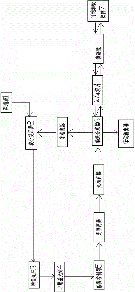
[0029] Such as figure 2 As shown, between the polarizing beam splitter 6 and the saturable absorber 7, a λ / 4 wave plate and a microlens are sequentially arranged.

[0030] A light collimator is provided between the polarization controller 5 and the polarization beam splitter 6 .

[0031] An optical isolator is provided between the polarization controller 5 and the optical collimator.

[0032] An optical collimator is provided between the polarization beam splitter 6 and the wavelength division multiplexer 2 .

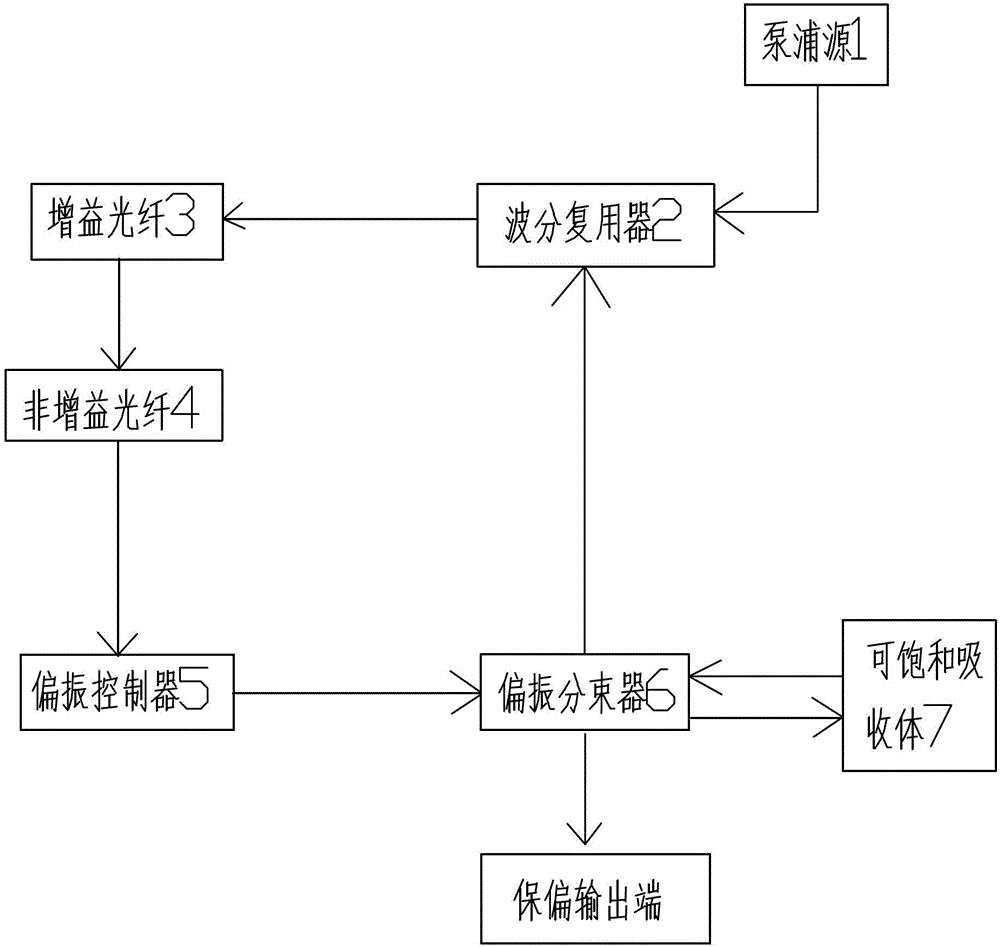
[0033] As mentioned above, this embodiment is a half-space half-fiber laser structure, using figure 2 The σ-cavity structure shown uses saturable absorbing mirrors and polarization rotation to achieve mode-locking.

[0034] In this embodiment, a semiconductor laser with a wavelength of 980nm is used for forward pumping, and is coupled into the optical path through a wavelength division multiplexer. In order to fully absorb, a highly doped ytterbium-doped fiber is u...

Embodiment 2

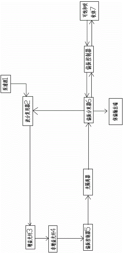
[0036] Such as image 3 As shown, a polarization controller is provided between the polarization beam splitter 6 and the saturable absorber 7 .

[0037] An optical isolator is provided between the polarization controller 5 and the polarization beam splitter 6.

[0038] As mentioned above, this embodiment is an all-fiber laser structure, using image 3 The σ-cavity structure shown uses saturable absorbing mirrors and polarization rotation to achieve mode-locking.

[0039]In this embodiment, a semiconductor laser with a wavelength of 980nm is used for forward pumping, and is coupled into the optical path through a wavelength division multiplexer. In order to fully absorb, a highly doped ytterbium-doped fiber is used as the gain medium. Single-mode fiber is used to control the repetition rate, and its length depends on the actual required pulse repetition rate. A polarization controller is used to change the polarization state of the laser. The light then passes through an op...

Embodiment 3

[0041] This embodiment is the control of the center wavelength, in figure 2 with image 3 In this method, the laser cavity structure is kept unchanged, and the saturable absorbing mirror and polarization rotation are used to achieve mode locking.

[0042] In this embodiment, a semiconductor laser with a wavelength of 980nm is used for forward pumping, a wavelength division multiplexer is used to couple the pump light into the optical path, a highly doped erbium-doped fiber is used as the gain medium, and a single-mode fiber with a center wavelength of 1550nm is used. Controls the repetition rate of the pulses. After passing through the single-mode fiber, the light enters the polarization controller to change the polarization state of the laser. Then the light passes through an optical isolator with a wavelength of 1550nm to ensure the unidirectional operation of the light, figure 2 In the process, the central wavelength of the optical collimator, λ / 4 glass slide, spatial ...


PUM


Abstract

The invention discloses a self-starting mode-locked fiber laser for polarization state stability control. The self-starting mode-locked fiber laser is characterized by comprising a pumping source 1, a wavelength division multiplexer 2, a gain fiber 3, a non-gain fiber 4, a polarization controller 5 and a polarization beam splitter 6 which are connected with one another in sequence, wherein the wavelength division multiplexer 2 is used for coupling pumping light and reflected light into a light path; the gain fiber 3 is used for generating inverted population required by laser; the non-gain fiber 4 is used for controlling the repletion frequency of the laser; the polarization controller 5 is used for changing a laser polarization state; and the polarization beam splitter 6 is used for dividing the laser into two beams. One laser output end of the polarization beam splitter 6 is connected with a saturable absorber 7 for generating nonlinear saturated absorption to realize mode-locked self-start, and the other laser output end of the polarization beam splitter 6 is a polarization-preserving output end; and the reflecting light of the saturable absorber 7 enters the wavelength division multiplexer 2 through the polarization beam splitter 6. The self-starting mode-locked fiber laser has the advantages that the mode-locked pulse sequence is more stable, the anti-interference capability is stronger, the laser can stably run for a long time, and the like, and the output of pulse laser with different repetition frequencies and center wavelengths is realized.

Description

[technical field] [0001] The invention relates to a self-starting mode-locked fiber laser with polarization state stabilization control [Background technique] [0002] Due to the characteristics of good gain characteristics, good output beam quality, small size, flexible use, and convenient connection with fiber optic communication systems, fiber lasers have been widely used in many fields. At present, the mode-locking methods commonly used in fiber pulse lasers include polarization rotation mode-locking and saturable absorption mode-locking, but they all have certain defects. Rotational mode-locking is unstable or even disappears, the obtained pulse has no long-term stability, and the modulation of the pulse sequence is quite large, so it cannot be self-started; saturable absorption mode-locking can realize mode-locked self-starting, but the obtained pulse is easy to split and has high noise. And the long time mode-locked pulse will cause damage to the saturable absorber. ...

Claims


Application Information

Patent Timeline
Patent Type & Authority Applications(China)
IPC IPC(8): H01S3/067H01S3/098H01S3/08H01S3/13
Inventor 梁崇智曾和平杨祥辉
Owner 广东华快光子科技有限公司
Why Eureka
Try Eureka