Laser plasma dual-use cutting machine

A plasma and cutting machine technology, used in plasma welding equipment, laser welding equipment, welding/cutting auxiliary equipment, etc. Good dust effect, solve the effect of laser instability

Active Publication Date: 2013-06-19
FOSHAN HONGSHI LASER TECH CO LTD
View PDF7 Cites 19 Cited by
  • Summary
  • Abstract
  • Description
  • Claims
  • Application Information

AI Technical Summary

Problems solved by technology

[0002] Existing CNC cutting machines mainly include two types of CNC laser cutting machines and CNC plasma cutting machines. The function is single, and the processing accuracy cannot be compared with the CNC laser cutting machine. Although the general laser and plasma dual-purpose cutting machine can combine the advantages of the two, due to the mutual interference of the cutting head settings, it can only be used interchangeably. It brings trouble, and the existing CNC laser cutting machine and CNC plasma cutting machine generally can only cut metal sheets. The position between the cutting head and the cutting head needs to be constantly adjusted, which poses a problem for plasma and laser cutting machines to cut pipes, so that plasma and laser cutting machines have not been widely used in pipe cutting
[0003] At the same time, during laser cutting, solid-state laser generators are generally used as lasers for metal cutting and welding. Solid-state laser generators generally include red light mirrors, reflectors, condenser cavities, half mirrors, beam expanders, etc. Solid-state laser generators Adjusting the distance between various mirrors in use is an important factor affecting the laser generation parameters. At the same time, because solid-state laser generators are widely used as metal cutting and welding lasers, the use environment i...

Method used


Image

  • Laser plasma dual-use cutting machine
  • Laser plasma dual-use cutting machine
  • Laser plasma dual-use cutting machine

Examples


Embodiment Construction

[0033] The present invention is described in further detail below in conjunction with the embodiment that accompanying drawing provides.

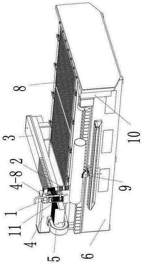
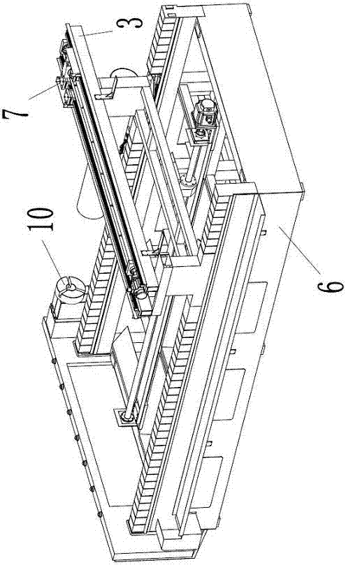
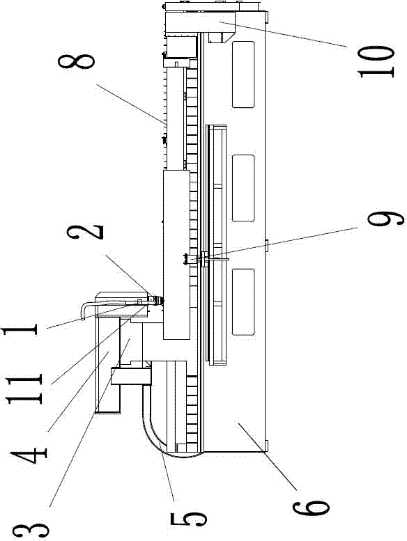
[0034] see figure 1 , 2 3. A laser and plasma dual-purpose cutting machine, comprising a bed 6, the bed 6 is connected with a beam 3, the beam 3 is connected with a drag plate 7, and the bed 6 is also fixedly connected with a workbench 8 and a drag Chain 5, its innovation lies in:

[0035] see figure 1 , 3 , 6, 7, 8, said carriage 7 is provided with a YAG solid-state laser generator 4, and the YAG solid-state laser generator 4 is provided with a light-emitting support plate 4-8, and said light-exit support plate 4-8 is equipped with two sets of Lifting mechanism 1, wherein one set of lifting mechanism 1 is connected with the double focal length laser cutting head 2, and the other set of lifting mechanism 1 is connected with plasma cutting torch 11;

[0036] see figure 1 , 2 , 3, 4, 5, the bed 6 is also provided with a rotary pipe cut...


PUM


Abstract

The invention discloses a laser plasma dual-use cutting machine which comprises a beam which is connected with a lathe bed in a transmission mode. A drag plate is connected with the beam in the transmission mode. A working table and a drag chain are fixedly connected with the lathe bed. An yttrium aluminum garnet (YAG) solid laser generator is arranged on the drag plate. The YAG solid laser generator is provided with a light dipping supporting plate. Two sets of lifting mechanisms are connected with the light dipping supporting plate in an installing mode, one set of lifting mechanisms is connected with a double-focal-distance cutting head in the installing mode, and the other set of lifting mechanisms is connected with a plasma cutting torch in the installing mode. The lathe bed is further provided with a rotary cutting pipe chuck and a rotary cutting pipe supporting frame. A laser cutting head and a numerical control plasma cutting head are both arranged on a numerical control cutting machine, and the laser cutting head and the numerical control plasma cutting head are reasonable in structure. Different processing requirements of workpieces can be met by the solid laser generator and the double-focal-distance cutting head, wherein the mirror spacing of the solid laser generator is convenient to adjust, the solid laser generator is good in dust-proof effect, and the double-focal-distance cutting head is capable of changing focal distances rapidly and high in processing precision. The laser plasma dual-use cutting machine particularly conducts cutting on metal tubular products.

Description

technical field [0001] The invention relates to an industrial cutting equipment, especially a laser plasma dual-purpose cutting machine Background technique [0002] Existing CNC cutting machines mainly include two types of CNC laser cutting machines and CNC plasma cutting machines. The function is single, and the processing accuracy cannot be compared with the CNC laser cutting machine. Although the general laser and plasma dual-purpose cutting machine can combine the advantages of the two, due to the mutual interference of the cutting head settings, it can only be used interchangeably. It brings trouble, and the existing CNC laser cutting machine and CNC plasma cutting machine generally can only cut metal sheets. The position between the cutting head and the cutting head needs to be constantly adjusted, which poses a problem for plasma and laser cutting machines to cut pipes, making plasma and laser cutting machines unable to be widely used in pipe cutting. [0003] At t...

Claims


Application Information

Patent Timeline
IPC IPC(8): B23K28/02B23K26/38B23K10/00B23K26/04B23K37/00B23K26/046
Inventor 吉保国
Owner FOSHAN HONGSHI LASER TECH CO LTD
Why Eureka
Try Eureka