
Water wall base cone assembly welding and heat treatment device and method

A technology of heat treatment device and heat treatment method, applied in heat treatment furnaces, heat treatment equipment, auxiliary devices, etc., can solve the problems of inability to meet use requirements, large welding stress and deformation, and achieve the effect of eliminating stress after surfacing and avoiding bending deformation.

Inactive Publication Date: 2013-06-19
KAIFENG AIR SEPARATION GROUP
View PDF5 Cites 6 Cited by
  • Summary
  • Abstract
  • Description
  • Claims
  • Application Information

AI Technical Summary

Problems solved by technology

However, the bottom cone of the water-cooled wall is composed of 64 circular welds, 128 fillet welds and a large-area circular surfacing layer. After welding, the overall high-temperature annealing treatment is required. The welding stress and deformation are very large, which cannot meet the use requirements.

Method used


Image

  • Water wall base cone assembly welding and heat treatment device and method
  • Water wall base cone assembly welding and heat treatment device and method
  • Water wall base cone assembly welding and heat treatment device and method

Examples


Embodiment 1

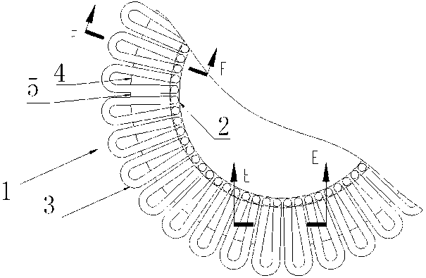
[0035] Such as figure 1 , 2 , 3, 4, 5, 6, 7, 8, 9, 10, a water-cooled wall bottom cone 1 set of butt welding, heat treatment device, the water-cooled wall bottom cone is composed of ring forging 2, special-shaped elbow 3, the first special-shaped The flat steel 4, the second special-shaped flat steel 5 and the annular surfacing layer 6 are formed by welding, and the device includes a docking device 7 and a welding heat treatment device 13; Four positioning blocks 10 for outer circle positioning and end face support positioning of the ring forging, positioning ring 8 and positioning ring 11 for positioning the inner stop and the outer stop of the base of the docking device through bolts, wherein the positioning block and the ring forging are positioned through bolts; The inner side of the locating ring contains an inner conical surface matched with the special-shaped elbow, and the outer conical surface of the special-shaped elbow cooperates with the inner conical surface of t...

Embodiment 2

[0038] A water-cooled wall bottom cone group butt welding and heat treatment method, the positioning and clamping structure of each workpiece and device is as follows Figure 6 , 7 , 8, 9, and 10, the steps of the method include:

[0039] Step 1. Connect the ring forging with the four directional blocks on the base of the docking device through bolts. The bolts pass through the channel of the ring forging to position the ring forging and clamp the ring forging. support positioning;

[0040] Step 2. The inner seam of the positioning ring cooperates with the outer seam of the base of the docking device for positioning, and the bolts are used for circumferential orientation and the positioning ring is clamped;

[0041] Step 3. Match the outer cone surface of the special-shaped elbow to be welded with the inner cone surface of the positioning ring, and connect the positioning ring and bolts to perform circumferential positioning. The two pipe ends of the special-shaped elbow are...


PUM


Abstract

The invention relates to a novel efficient gasifier water wall connecting base cone assembly welding and heat treatment method and a device. A water wall base cone 1 is formed by an annular forge piece 2, abnormal-shaped bend pipes 3, first deformed flat steel, second deformed flat steel and an annular deformed flat steel layer 6. The method includes a first step of enabling pipe ports of at both ends of the thirty-two abnormal-shaped bend pipes are in butt joint with two channels adjacent to the annular forge pipe, and then enabling the first deformed flat steel and the second deformed flat steel to be alternatively welded with the inner sides of the abnormal-shaped bend pipes to form a circular abnormal-shaped surface, a second step of enabling a heat-resisting layer of 3 millimeters in thickness to be subjected to bead weld on the connected circular abnormal-shaped surface, and a third step of sending the welded water wall base cone into a furnace to carry out high-temperature tempering processing. The water wall base cone assembly welding and heat treatment device and the method reduce deformation and bend in the welding process of the water wall base cone, and ensure a geometrical shape after the water wall base cone is welded.

Description

technical field [0001] The present invention relates to the welding method of the bottom cone of the water-cooled wall, and in particular to a new butt welding, heat treatment device and method for connecting the bottom cone group of the water-cooled wall of a high-efficiency gasification furnace. Background technique [0002] The coal chemical industry is playing an increasingly important role in the national economy; the internal parts of the "gasifier" are mainly composed of multi-section cylindrical water-cooled membrane walls; Components of cylindrical membrane wall and auxiliary chiller. [0003] The bottom cone of the water-cooled wall is composed of ring forgings, special-shaped elbows, special-shaped flat steel, special-shaped flat steel, and surfacing layer through welding. In order to eliminate the stress after surfacing, post-weld heat treatment is also required. The other end of the ring-shaped forging in the bottom cone of the water-cooled wall is connected to...

Claims


Application Information

Patent Timeline
Patent Type & Authority Applications(China)
IPC IPC(8): B23K31/02B23K37/04C21D9/50
Inventor 徐纪高周礼新冷雪峰齐浩王鸿雁
Owner KAIFENG AIR SEPARATION GROUP
Learn More