
Device and method for detecting optical interference of light polarization tiny corner

A micro-angle, optical interference technology, applied in measuring devices, optical radiation measurement, measuring the polarization of light, etc., can solve the problems of weak detection signal, weak light intensity, limited detection sensitivity, etc.

Active Publication Date: 2013-06-19
杭州诺驰生命科学有限公司
View PDF4 Cites 17 Cited by
  • Summary
  • Abstract
  • Description
  • Claims
  • Application Information

AI Technical Summary

Problems solved by technology

In order to achieve highly sensitive magnetic field and inertial measurement, the light intensity of the detection light is usually relatively weak in the scientific research of the current atomic magnetometer and atomic spin gyroscope, and usually only a beam of linearly polarized light is used for detection, and there is no Using the optical interference measurement scheme of two beams of light in the fiber optic gyroscope results in a relatively weak part of the useful detection signal, which limits the further improvement of its detection sensitivity to a certain extent

Method used


Image

  • Device and method for detecting optical interference of light polarization tiny corner
  • Device and method for detecting optical interference of light polarization tiny corner
  • Device and method for detecting optical interference of light polarization tiny corner

Examples


Embodiment Construction

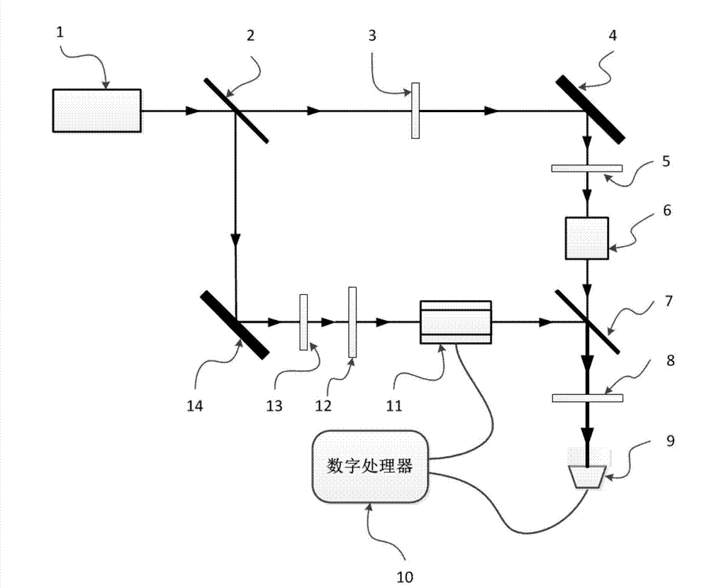
[0068] Such as figure 1 As shown, the detection device of the present invention includes a laser 1, a beam splitter 2, a first half-wave plate 3, a first mirror 4, a first polarizer 5, an optically active medium 6, a depolarization beam splitter prism 7, and an analyzer device 8, photodetector 9, digital processor 10, light polarization direction modulation assembly 11, second polarizer 12, second half-wave plate 13 and second reflector 14; the first polarizer 5 is placed on The rear side of the first reflector 4, the second polarizer 12 is placed on the rear side of the second reflector 14, the light transmission directions of the first polarizer 5 and the second polarizer 12 are all consistent with the transmission of the analyzer 8 The light direction is vertical; the depolarization beam splitter 7 is a depolarization beam splitter with a reflectivity / transmittance of 50 / 50; beam splitter 2, the first half-wave plate 3, the first polarizer 5, and the second half-wave One w...


PUM


Abstract

The invention relates to a device and a method which are formed through combining a light polarization direction modulation component with optical interference and used for detecting a light polarization tiny corner. A light beam generated by a laser device becomes two bunches of linearly polarized light after passing through a beam splitter and a polarizer, wherein a tiny corner can be added on the polarization direction of one bunch of light after the bunch of light passes through optical rotation mediums, the polarization direction of the other bunch of light is modulated after the light passes through the light polarization direction modulation component, then the two bunches of light become two bunches of coherent light beams after passing through a depolarizing beam splitting prism and a polarization analyzer, the two bunches of coherent light become electrical signals after entering into a photoelectric detector, and a digital processor is used for extracting and calculating first harmonic and second harmonics signals in electrical signals, the first and second harmonics signals are consistent with modulation frequency of the modulation component, and therefore measurement of the light polarization tiny corner is achieved. The device and a method which are formed through combining a light polarization direction modulation component with optical interference achieve optical enlargement of light polarization tiny corner signals, and can be used in precision measurement of light polarization tiny corners through instruments of atomic spin magnetometers, atomic spin gyroscopes and the like.

Description

technical field [0001] The invention relates to an optical interference detection device and method for a small rotation angle of light polarization, which can be used as a precision measurement device and method for a small rotation angle of light polarization in instruments and equipment such as atomic magnetometers and atomic spin gyroscopes, and can also be used for magnetic Precise measurement of optical crystal Verdet coefficient and other parameters. Background technique [0002] The fiber optic gyroscope based on the Sagnac effect uses the change of the optical interference signal caused by the phase difference between the two beams of light to realize the precise measurement of the carrier rotation signal. At present, most fiber optic gyroscopes use piezoelectric ceramic fiber optic phase modulators to modulate the phase of light. The phase shift of the two beams of light caused by the rotation of the carrier is extracted through the lock-in amplifier module to obta...

Claims


Application Information

Patent Timeline
Patent Type & Authority Applications(China)
IPC IPC(8): G01J4/04
Inventor 房建成李茹杰胡朝晖万双爱陈瑶全伟
Owner 杭州诺驰生命科学有限公司
Learn More