Positive pole piece and preparation method thereof and battery
A positive electrode plate, positive electrode active technology, applied in the direction of battery electrodes, circuits, electrical components, etc., can solve the problems of greater safety and hidden dangers of batteries, and achieve the effect of increasing internal resistance
- Summary
- Abstract
- Description
- Claims
- Application Information
AI Technical Summary
Problems solved by technology
Method used
Image
Examples
preparation example Construction
[0025] At the same time, the present invention also discloses a method for preparing the above-mentioned positive electrode sheet, including:
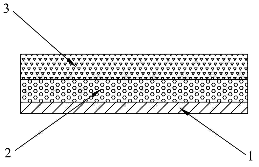
[0026] S1. Mix the phosphate, the first conductive agent, and the first binder uniformly in a mass ratio of 40-90:5-10:5-50, and add a solvent to obtain a buffer conductive layer slurry, wherein the buffer conductive layer slurry The solid content is 10-50%, and the viscosity is 200-1500Pa·s;
[0027] S2, coating the buffer conductive layer slurry on the positive electrode current collector, baking, and forming a buffer conductive layer with a thickness of 2-50 μm on the positive electrode current collector;
[0028] S3, forming a positive electrode active layer on the surface of the buffer conductive layer.
[0029] The solvent in the above step S1 is N-methylpyrrolidone or deionized water.
[0030] In the present invention, as in step S1, when preparing the buffer conductive layer, the solid content is adjusted to 10-50%, and the v...
Embodiment 1
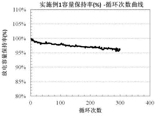
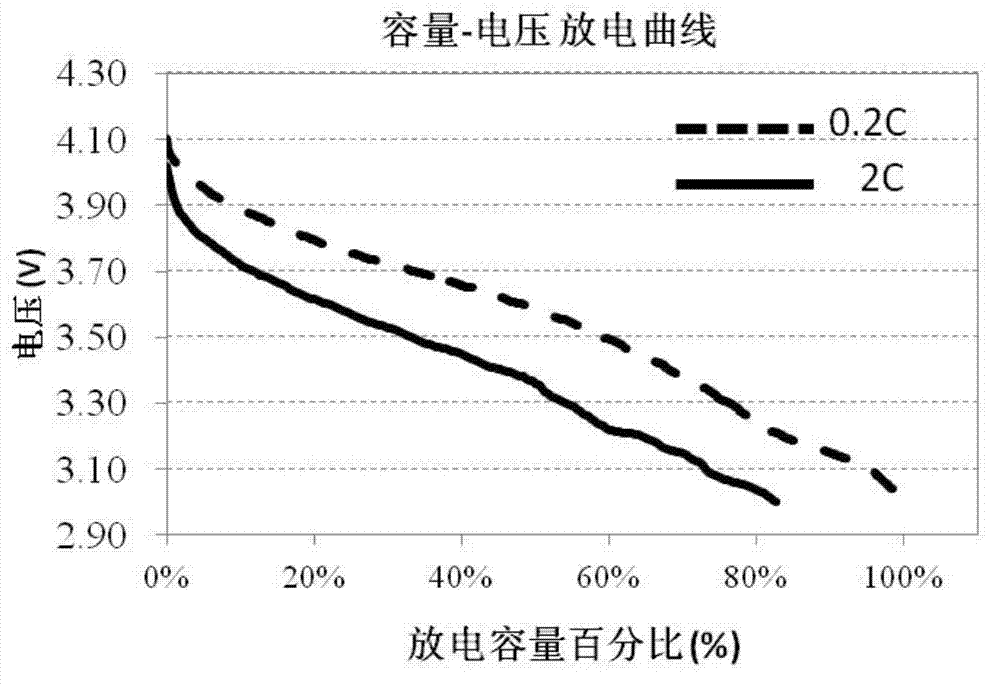
[0045] This embodiment is used to illustrate the positive electrode sheet disclosed in the present invention and its preparation method.
[0046] Buffer conductive layer slurry preparation:
[0047] 16 g LiCoPO 4 active material (D 50 Less than 5μm), 4 grams of conductive carbon powder Super-P (D 50 less than 50 μm), 20 grams of binder PAA, mixed with 60 grams of deionized water and stirred to adjust the viscosity to 800-1200 Pa·s, and passed through a 200-mesh sieve. Coated on a 14μm aluminum foil current collector and baked in vacuum at 85°C for 1 hour. A buffer conductive layer was formed to a thickness of 25 μm.
[0048] Positive pole piece preparation:
[0049] Weigh 95 grams of lithium cobaltate active material, 2 grams of conductive carbon powder, and 3 grams of binder PVDF to mix, add 200 grams of NMP and stir to obtain active material slurry, and coat it on the aluminum aggregate treated with coating slurry On the fluid, control the drying temperature and coatin...
Embodiment 2
[0057] This embodiment is used to illustrate the positive electrode sheet disclosed in the present invention and its preparation method.
[0058] Buffer conductive layer slurry preparation:
[0059] 16 g LiFePO 4 active material (D 50 Less than 2μm), 4 grams of conductive carbon powder Super-P (D 50 less than 50 μm), 20 grams of binder PAA, mixed with 60 grams of deionized water and stirred to adjust the viscosity to 800-1200 Pa·s, and passed through a 200-mesh sieve. Coated on a 14μm aluminum foil current collector and baked in vacuum at 85°C for 1 hour. A buffer conductive layer was formed to a thickness of 25 μm.
[0060] The positive electrode sheet preparation, battery preparation method and testing method are the same as in Example 1.
PUM
| Property | Measurement | Unit |
|---|---|---|
| thickness | aaaaa | aaaaa |
| particle diameter | aaaaa | aaaaa |
| particle diameter | aaaaa | aaaaa |
Abstract
Description
Claims
Application Information
 - R&D
- Intellectual Property
- Life Sciences
- Materials
- Tech Scout
- Unparalleled Data Quality
- Higher Quality Content
- 60% Fewer Hallucinations
Browse by: Latest US Patents, China's latest patents, Technical Efficacy Thesaurus, Application Domain, Technology Topic, Popular Technical Reports.
© 2025 PatSnap. All rights reserved.Legal|Privacy policy|Modern Slavery Act Transparency Statement|Sitemap|About US| Contact US: help@patsnap.com


