Boosted circuit, backlight driver circuit and backlight module

A booster circuit and booster chip technology, applied in the field of signal control, can solve problems such as the fixed output voltage of the booster circuit and the inability to track the change of the input voltage.

Active Publication Date: 2013-06-19
BOE TECH GRP CO LTD +1
View PDF5 Cites 16 Cited by
  • Summary
  • Abstract
  • Description
  • Claims
  • Application Information

AI Technical Summary

Problems solved by technology

[0007] The embodiment of the present invention provides a boost circuit to solve the problem in the prior art that the output voltage of the boost circuit is fixed and cannot track the change of the input voltage

Method used


Image

  • Boosted circuit, backlight driver circuit and backlight module
  • Boosted circuit, backlight driver circuit and backlight module

Examples


Embodiment Construction

[0026] The embodiments of the present invention will be further described below in conjunction with the accompanying drawings, but the present invention is not limited to the following embodiments.

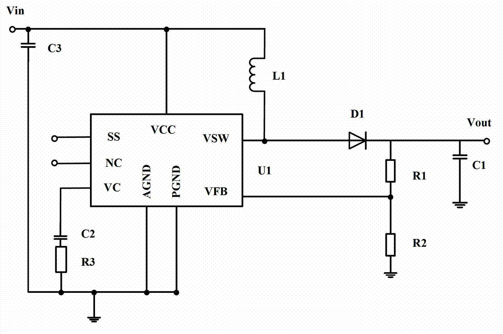
[0027] Embodiments of the present invention provide a new boost circuit based on the existing boost circuit, such as figure 2 As shown, it is a schematic structural diagram of the boost circuit in the embodiment of the present invention, and the boost circuit includes:

[0028] Boost chip U1, energy storage inductor L1, freewheeling diode D1, and first capacitor C1, wherein one end of the energy storage inductor L1 is connected to the signal input terminal (Vin) of the boost circuit, and the other end is connected to the boost chip U1 The high current switch pin (Vsw) is connected and the other end of the energy storage inductor L1 is also connected to the signal output end (Vout) of the boost circuit through the freewheeling diode D1; one end of the first capacitor C1 is connect...


PUM


Abstract

The invention discloses a boosted circuit, a backlight driver circuit and a backlight module, the boosted circuit comprises a boosted chip, an energy storage inductor, a freewheel diode, a first capacity and a current mirror unit, wherein an input end of an input branch of the current mirror unit and an input end of an output branch of the current mirror unit are respectively connected with the negative pole of the freewheel diode, the output end of the input branch is connected with the signal input end of a boosted chip through a first resistor, the output end of the output branch is connected with ground through a second resistor, and the non-ground-connecting end of the second resistor is connected with the signal feedback pin end of the boosted chip. According to the technical scheme of the boosted circuit, the backlight driver circuit and the backlight module, due to the fact that the current mirror unit is added at the signal output end side of the boosted circuit, changing tracking of the output voltage to the input voltage is achieved on the premise that parameter of each device in the original boosted circuit is not changed, and the effect that difference of the output voltage and the input voltage is fixed is achieved.

Description

technical field [0001] The present invention relates to the technical field of signal control, in particular to a voltage difference fixed boost circuit based on an existing boost circuit, a backlight drive circuit and a backlight module. Background technique [0002] At present, in application circuits such as liquid crystal displays, it is usually necessary to drive the LED (Light Emitting Diode, light-emitting diode) of the backlight of the liquid crystal display through a boost circuit, and the brightness of the LED can usually be adjusted according to the display requirements of the display screen in different situations. degree. [0003] Specifically, such as figure 1 As shown, it is a schematic diagram of the basic structure of the boost circuit in the prior art. The boost circuit includes a boost chip U1, an energy storage inductor L1, a freewheeling diode D1, a first capacitor C1, a second capacitor C2, The third capacitor C3, the first resistor R1, the second res...

Claims


Application Information

Patent Timeline
Patent Type & Authority Applications(China)
IPC IPC(8): H02M3/155G09G3/34H05B44/00
CPCG09G3/34H02M3/156H02M3/1563G09G2330/02H05B45/37H05B45/397Y02B20/30
Inventor 张斌张亮胡巍浩
Owner BOE TECH GRP CO LTD
Why Eureka
Try Eureka