Non-linear correction method for LFMCW (linear frequency modulated continuous wave) laser radar frequency modulation based on optical fiber sampling technology

A nonlinear correction and lidar technology, applied in the field of nonlinear correction, can solve problems such as inability to perform nonlinear correction

Active Publication Date: 2013-06-26
HARBIN INST OF TECH
View PDF12 Cites 14 Cited by
  • Summary
  • Abstract
  • Description
  • Claims
  • Application Information

AI Technical Summary

Problems solved by technology

[0004] In order to solve the problem that nonlinear correction cannot be performed when the frequency modulation curve changes unevenly, t...

Method used


Image

  • Non-linear correction method for LFMCW (linear frequency modulated continuous wave) laser radar frequency modulation based on optical fiber sampling technology
  • Non-linear correction method for LFMCW (linear frequency modulated continuous wave) laser radar frequency modulation based on optical fiber sampling technology
  • Non-linear correction method for LFMCW (linear frequency modulated continuous wave) laser radar frequency modulation based on optical fiber sampling technology

Examples


specific Embodiment approach 1

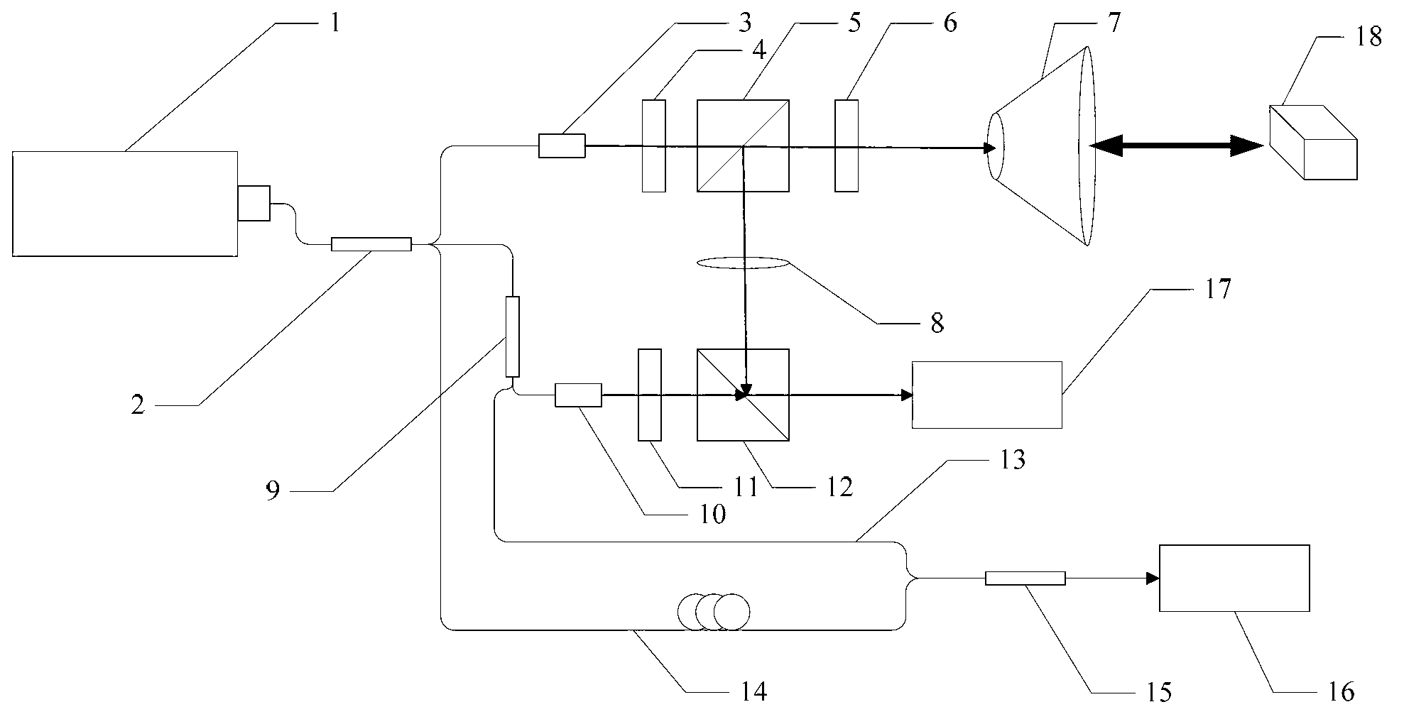
[0022] Specific implementation mode one: combine figure 1 and Figure 8 Describe this embodiment, the nonlinear correction method of LFMCW laser radar frequency modulation based on optical fiber sampling technology described in this embodiment, the LFMCW laser radar is an LFMCW laser radar with a correction optical path, which includes an interferometric optical path and a correction optical path, The interferometric optical path includes a tuning laser 1, a first coupler 2, a first collimating mirror 3, a first glass slide 4, a first polarizing beam splitter 5, a second glass slide 6, a collimating beam expander 7, a focusing A lens 8, a second coupler 9, a second collimating mirror 10, a third glass slide 11, a second polarization beam splitter 12 and a second detector 17, and the correction optical path includes a first optical fiber 13, a second optical fiber 14, The third coupler 15 and the first detector 16,

[0023] The linear continuous frequency-modulated laser lig...

specific Embodiment approach 2

[0032] Embodiment 2: This embodiment is a further limitation of the non-linear correction method for LFMCW lidar frequency modulation based on fiber sampling technology described in Embodiment 1, and the tuned laser 1 is a 1550nm tuned laser.

specific Embodiment approach 3

[0033] Embodiment 3: This embodiment is a further limitation of the non-linear correction method of LFMCW laser radar frequency modulation based on fiber sampling technology described in Embodiment 1, and the first coupler 2 is a 1×3 coupler.


PUM


Abstract

The invention discloses a non-linear correction method for LFMCW (linear frequency modulated continuous wave) laser radar frequency modulation based on an optical fiber sampling technology, and relates to the technical field of LFMCW laser radar frequency modulation and non-linear correction. The method solves the problems that non-linear correction cannot be performed when frequency modulation curve changes are not gradual. Lengths of a first optical fiber and a second optical fiber in a correction optical path are calibrated in advance, the length difference of the first optical fiber and the second optical fiber is the maximum measuring distance of an LFMCW laser radar, namely the measuring range upper limit, a third coupler combines beams of the first optical fiber and the second optical fiber, and correction light is received by a first probe to form a beat frequency signal. After the beat frequency signal is subjected to electrical frequency doubling, beat frequency signals in an interferometry optical path are sampled, and then the sampled signals are subjected to signal processing, so that influences, of frequency modulation non-nonlinearity of a frequency modulation laser, on measuring results are eliminated. The method is suitable for laser radar frequency modulation non-linear correction.

Description

technical field [0001] The invention relates to the technical field of nonlinear correction of LFMCW laser radar frequency modulation. Background technique [0002] The linear frequency modulated continuous wave (LFMCW) laser radar has outstanding advantages such as low transmission power, low intercept probability, unambiguous ranging, and high-resolution range, so it has been widely used in the field of precision guidance. The basic principle is to use the frequency difference between the transmitted signal and the echo signal to determine the target distance, that is, rely on the easier-to-process signal frequency domain characteristics to reflect the target's distance parameters. The ideal linear broadband modulation waveform can obtain very high distance resolution, but this system has extremely strict requirements on the modulation linearity, and the nonlinear component will inevitably have a negative impact on the system, resulting in inaccurate measurement of distanc...

Claims


Application Information

Patent Timeline
IPC IPC(8): G01S7/40
Inventor 甘雨陈凤东许新科刘国栋刘炳国庄志涛
Owner HARBIN INST OF TECH
Why Eureka
Try Eureka