Detecting device, detecting system, power transmitting device, noncontact power transmission system, and detecting method

A technology of testing equipment and equipment, applied in the direction of measuring resistance/reactance/impedance, electromagnetism, electromagnetic wave system, etc., can solve the problems of imposing design restrictions, high cost, etc., and achieve the effect of simple structure

Active Publication Date: 2013-06-26
SONY CORP
View PDF8 Cites 25 Cited by
  • Summary
  • Abstract
  • Description
  • Claims
  • Application Information

AI Technical Summary

Problems solved by technology

However, the detection method using sensors entails high costs as in magnetic field resonance systems in the case of a wide feeding range
In the case of a temperature sensor, for example, the output result of the temperature sensor depends on the thermal conductivity around the temperature sensor, thereby imposing design constraints on the devices on the power transmitting side and the power receiving side

Method used


Image

  • Detecting device, detecting system, power transmitting device, noncontact power transmission system, and detecting method
  • Detecting device, detecting system, power transmitting device, noncontact power transmission system, and detecting method
  • Detecting device, detecting system, power transmitting device, noncontact power transmission system, and detecting method

Examples


no. 1 example

[0069] 【Example of configuration of detection system】

[0070] A detection system for realizing the metal foreign matter detection method described above will be described.

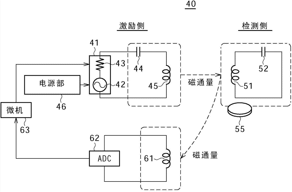
[0071] figure 2 is a schematic circuit diagram showing an example of the configuration of the detection system according to the first embodiment of the present disclosure. figure 2 The illustrated circuit is a basic configuration describing an outline of detecting a metal foreign substance by measuring a Q value according to the first embodiment of the present disclosure. However, the present disclosure is not limited to this example.

[0072] The detection system 40 according to the present embodiment is divided into two parts on the excitation side and the detection side.

[0073] The excitation side includes an excitation unit and a Q value measurement unit. The excitation section includes: a signal source 41 including a signal generator 42 and a resistance element 43 for generating an AC signal;...

no. 2 example

[0169] 【Example of configuration of non-contact power transmission system】

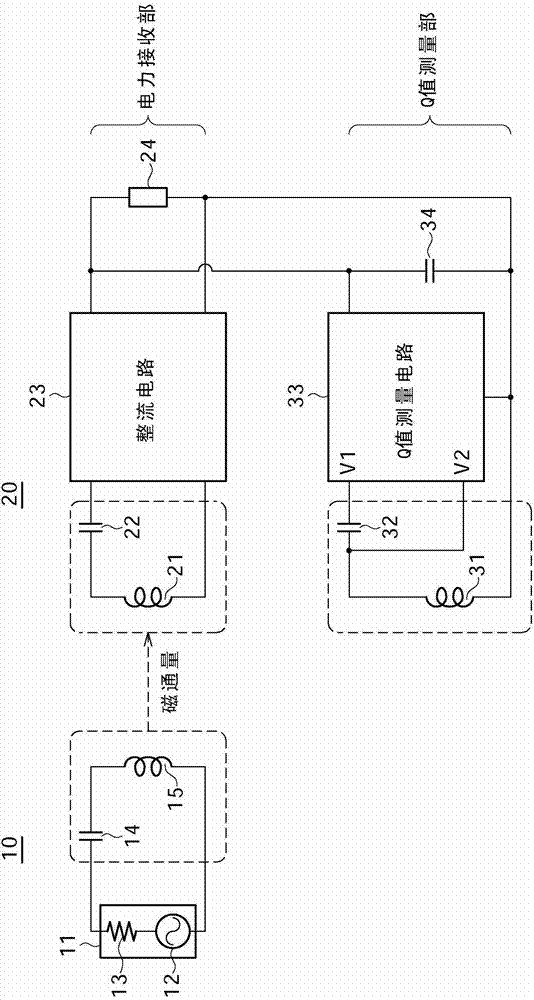
[0170] Figure 7 A schematic circuit diagram showing an example of a configuration of a non-contact power transmission system employing a detection system according to an embodiment of the present disclosure. identified by the same reference number Figure 7 neutralize figure 1 and figure 2 The constituent elements in have substantially the same function and configuration, and repeated descriptions of these constituent elements will be omitted.

[0171] By adding read coil 61 to the figure 1 The power transmission device 10 shown to form Figure 7 A power transmission device 10A of a non-contact power transmission system is shown. The reading coil 61 is configured to detect magnetic flux generated by the power receiving coil 21 (secondary side coil) according to the magnetic field received by the power receiving coil 21 from the power transmitting coil 15 (primary side coil). through from fig...

no. 3 example

[0180] The third embodiment is wherein according to the second embodiment (see Figure 7 ) The power transmission coil 15 in the power transmission device 10A is also used as an example of the read coil 61 .

[0181] Figure 8 is a schematic circuit diagram showing an example of the configuration of a non-contact power transmission system according to a third embodiment of the present disclosure.

[0182] Figure 8 The power transmitting device 10B shown in has a switch 83 (an example of a switching section) so that the power transmitting coil 15 functions as both a power transmitting coil and a reading coil. According to a switching signal from the control unit of the microcomputer 16, the circuit connected to the power transmission coil 15 is switched between the power transmission unit side and the Q value measurement unit side. Incidentally, a switching element such as a transistor, MOSFET, or the like can be used as an example of the switch 83 .

[0183] Furthermore, ...


PUM


Abstract

A detecting device includes a reading coil configured to read a magnetic flux generated by a detecting coil for detecting a magnetic field of an electromagnetic wave output from an exciting coil according to the magnetic field. The detecting device further includes a Q-value measuring section configured to measure a Q-value of the detecting coil on a basis of a temporal transition of oscillation of a voltage obtained in the reading coil according to the magnetic flux generated by the detecting coil.

Description

technical field [0001] The present disclosure relates to a detection device, a detection system, a power transmission device, a non-contact power transmission system, and a detection method for detecting the presence of a conductor such as metal. Background technique [0002] Recently, non-contact power transmission systems in which power is supplied on a non-contact basis (wireless power feeding) have been actively developed. Systems for realizing wireless power feeding are roughly classified into two methods. [0003] One is the commonly known electromagnetic induction system. In the electromagnetic induction system, the degree of coupling between the power transmitting side and the power receiving side is high, and thus power feeding can be performed with high efficiency. However, the coupling coefficient between the power transmitting side and the power receiving side needs to be kept high. Therefore, when the distance between the power transmitting side and the power...

Claims


Application Information

Patent Timeline
Patent Type & Authority Applications(China)
IPC IPC(8): G01V3/12H02J17/00H02J7/00G01R27/26
CPCG01V3/12G01R27/2688H02J50/12H02J50/60G01R33/028G01R33/0283
Inventor 迂山伸二
Owner SONY CORP
Why Eureka
Try Eureka