Gas-seal and gas-liquid vibration damping recovery device used in immersion lithographic machine

A recovery device and air-sealing technology, which is applied in the field of flow field sealing and recovery devices, can solve problems such as liquid leakage, flow field edge instability, and sealing gas entrainment, so as to prevent liquid leakage, continuously and stably update, reduce fluctuating effect

Active Publication Date: 2013-06-26
ZHEJIANG CHEER TECH CO LTD
View PDF5 Cites 5 Cited by
  • Summary
  • Abstract
  • Description
  • Claims
  • Application Information

AI Technical Summary

Problems solved by technology

During the high-speed movement of the substrate, once the external air or sealing liquid is involved or dissolved or diffused into the filling liquid, it will have a negative impact on the exposure quality
[0005] (2) The existing air sealing method uses an air curtain to apply around the filling fluid, causing instability at the edge of the flow field. During the high-speed stepping and scanning process of the substrate, it may cause liquid leakage and entrainment of sealing gas to the flow field At the same time, when the filling liquid and the sealing gas are recovered together, a gas-liquid two-phase flow will be formed, which will cause vibration and affect the stable operation of the exposure system
[0006] In the existing solution, the air seal is better, but the existing air seal device has the problem of gas-liquid two-phase flow in the recovery process, and the recovery of the two together will cause the vibration of the pipeline. thus seriously affecting the exposure quality

Method used


Image

  • Gas-seal and gas-liquid vibration damping recovery device used in immersion lithographic machine
  • Gas-seal and gas-liquid vibration damping recovery device used in immersion lithographic machine
  • Gas-seal and gas-liquid vibration damping recovery device used in immersion lithographic machine

Examples


Embodiment Construction

[0034] The specific implementation process of the present invention will be described in detail below in conjunction with the drawings and embodiments.

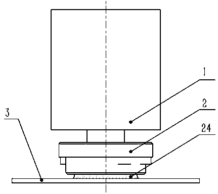
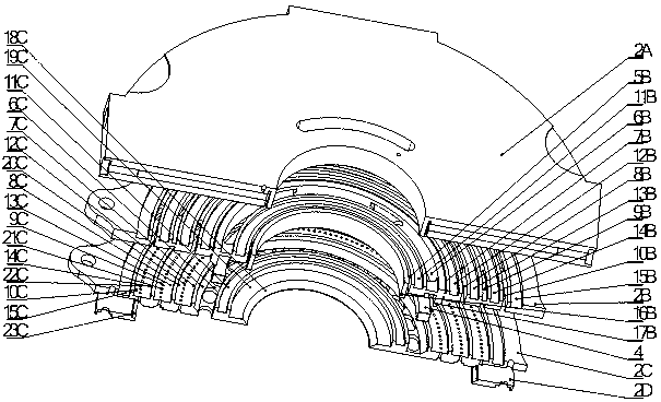
[0035] Such as figure 1 As shown, an air-tight and gas-liquid vibration damping recovery device is installed between the projection objective lens group 1 and the silicon wafer 3 in the immersion lithography machine; the gas-liquid damping recovery device includes a sealing and liquid injection recovery device 2. Porous medium 4; the sealing and liquid injection recovery device 2 consists of the upper end cover 2A of the immersion unit, the intermediate body 2B of the immersion unit, the lower end cover 2C of the immersion unit and the lower end cover accessory 2D of the immersion unit; wherein:

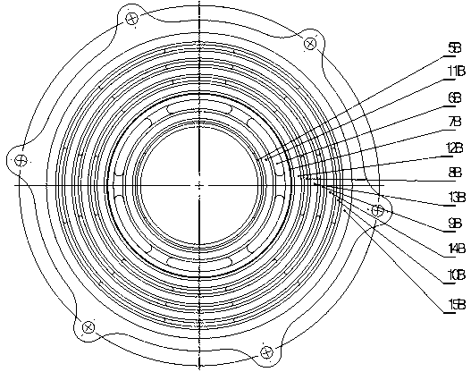
[0036] 1) Upper end cover 2A of the immersion unit:

[0037] Such as Image 6 As shown, there is a central through hole in the upper end cover 2A of the immersion unit, and two symmetrical liquid injection tanks 5A are opened in s...


PUM


Abstract

The invention discloses a gas-seal and gas-liquid vibration damping recovery device used in an immersion lithographic machine. The gas-seal and gas-liquid vibration damping recovery device is arranged between a projection lens group of the immersion lithographic machine and a silicon wafer; the gas-seal and gas-liquid vibration damping recovery device comprises a sealing and injected liquid recovery device, and a porous medium. The sealing and injected liquid recovery device is composed of an immersion unit upper end cap, an immersion unit middle body, an immersion unit lower end cap, and immersion unit lower end cap parts. The device provided by the invention is used for accomplishing functions of sealing and injected liquid recovery of a gap flow field of an immersion lithographic system, such that gap flow field continuous and stable renewing can be realized. The gas seal structure is adopted in the edge of the gap flow field, such that liquid leakage is prevented; with the gas-liquid vibration damping recovery structure, gas and liquid recovery are realized; under a condition of low speed, the appearance of a gas-liquid two-phase flow is avoided; under a condition of high speed, vibration caused by gas-liquid two-phase flow is reduced; no matter what direction the silicon moves in, with a buffering cavity structure, the gap flow field has a self-adaptive adjusting function.

Description

technical field [0001] The invention relates to a flow field sealing and recovery device, in particular to an air sealing and gas-liquid vibration damping recovery device for an immersion photolithography machine. Background technique [0002] The lithography machine is one of the core equipment for manufacturing VLSI. The modern lithography machine is mainly optical lithography. It uses the optical system to accurately project and expose the pattern on the mask to the photoresist-coated surface. on a silicon wafer. It includes a laser light source, an optical system, a projection mask composed of chip patterns, an alignment system and a silicon wafer coated with photosensitive photoresist. [0003] Immersion lithography (Immersion Lithography) equipment fills a liquid with a high refractive index between the last projection objective lens and the silicon wafer, which improves the numerical aperture of the projection objective lens ( NA), thereby improving the resolution a...

Claims


Application Information

Patent Timeline
Patent Type & Authority Applications(China)
IPC IPC(8): G03F7/20
Inventor 傅新马颖聪陈文昱徐宁
Owner ZHEJIANG CHEER TECH CO LTD
Why Eureka
Try Eureka