
Radio frequency MEMS (micro-electromechanical system) switch and forming method thereof

A switch and radio frequency technology, which is applied in the direction of electric switches, relays, electrostatic relays/electro-adhesion relays, etc., can solve the problems of switch burnout, burnout, etc., and achieve the effects of increasing switch power capacity, improving electrical contact, and improving thermal failure

Active Publication Date: 2013-06-26
TSINGHUA UNIV
View PDF3 Cites 34 Cited by
  • Summary
  • Abstract
  • Description
  • Claims
  • Application Information

AI Technical Summary

Problems solved by technology

For traditional contact RF MEMS switches that use metal-to-metal direct contact to control the on and off of RF signals, the heat caused by micro-fusion welding or switch burnout caused by excessive input power in the on-state The failure problem is the main factor restricting its power capacity, and the large contact resistance between metal and metal is the main source of local high temperature, which leads to micro-fusion welding or even burning problems

Method used


Image

  • Radio frequency MEMS (micro-electromechanical system) switch and forming method thereof
  • Radio frequency MEMS (micro-electromechanical system) switch and forming method thereof

Examples


Embodiment Construction

[0028] Embodiments of the present invention are described in detail below, examples of which are shown in the drawings, wherein the same or similar reference numerals designate the same or similar elements or elements having the same or similar functions throughout. The embodiments described below by referring to the figures are exemplary and are intended to explain the present invention and should not be construed as limiting the present invention.

[0029] In describing the present invention, it should be understood that the terms "center", "longitudinal", "transverse", "length", "width", "thickness", "upper", "lower", "front", " Orientation or position indicated by "back", "left", "right", "vertical", "horizontal", "top", "bottom", "inner", "outer", "clockwise", "counterclockwise", etc. The relationship is based on the orientation or positional relationship shown in the drawings, and is only for the convenience of describing the present invention and simplifying the descrip...


PUM

PropertyMeasurementUnit
Thicknessaaaaaaaaaa

Abstract

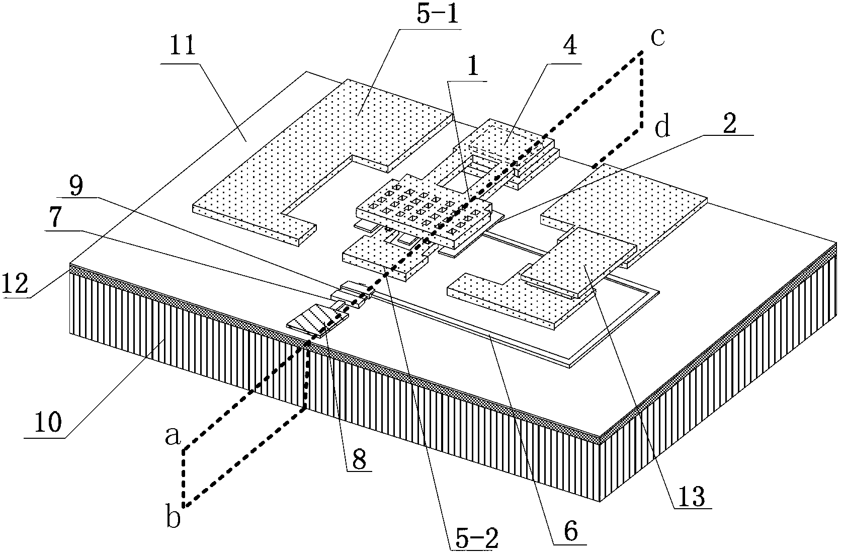
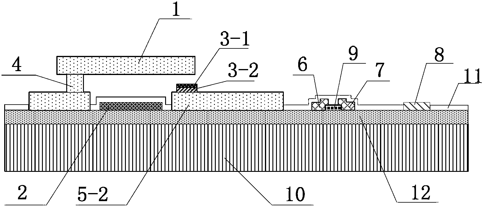
The invention provides a radio frequency MEMS (micro-electromechanical system) switch and a forming method thereof. The switch comprises a substrate, a barrier layer formed on the substrate, a drive electrode, a microwave signal coplanar waveguide transmission line and a metal cantilever beam arm formed on the microwave signal coplanar waveguide transmission line, the drive electrode and the microwave signal coplanar waveguide transmission line are formed on the substrate, the microwave signal coplanar waveguide transmission line is provided with a switch contact point and an anchor region, the position of the switch contact point corresponds to a free end of the metal cantilever beam arm, the anchor region corresponds to a fixed end of the metal cantilever beam arm, and the switch contact point is composed of a copper film and a graphene film formed on the copper film. When the drive electrode is not applied with drive voltage, the metal cantilever beam arm is disconnected with the switch contact point to enable the switch to be off, and when the drive electrode is applied with drive voltage, electrostatic force is generated between the metal cantilever beam arm and the drive electrode, and the metal cantilever beam arm is enabled to bend to contact with the switch contact point so as to enable the switch to be on. The switch and the method have the advantages of lower thermal failure and high power capacity of the switch.

Description

technical field [0001] The invention belongs to the field of radio frequency microelectromechanical systems (MEMS), and in particular relates to a radio frequency MEMS switch and a forming method thereof. Background technique [0002] RF MEMS (Micro-Electro-Mechanical Systems, RF Micro-Electro-Mechanical Systems) switch is a radio-frequency switch made using MEMS technology. It controls the on and off of radio-frequency signals through the movement of micro-mechanical structures. RF MEMS switch is one of the core devices of microwave and radio frequency transceiver systems, and has a wide range of applications in satellite communication, radar, missile control and other fields. Compared with traditional PIN and FET microwave switch devices, MEMS switches not only have extremely excellent microwave performance such as high isolation, low loss, low insertion loss, and high linearity, but also have mass production, small size, and easy integration with The characteristics of a...

Claims


Application Information

Patent Timeline
IPC IPC(8): H01H59/00H01H11/00
Inventor 刘泽文赵晨旭
Owner TSINGHUA UNIV
Learn More