loop reactor
A loop reactor, photobioreactor technology, applied in photobioreactor, bioreactor/fermenter combination, bioreactor/fermenter for specific purposes, etc., can solve the problem of increasing the complexity of the breeding system and the difficulty of cleaning Large, uneven aeration and other problems, to reduce the cost of manual cleaning, simplify the stirring system, and prevent microalgae from adhering to the wall
- Summary
- Abstract
- Description
- Claims
- Application Information
AI Technical Summary
Problems solved by technology
Method used
Image

Examples
no. 1 example
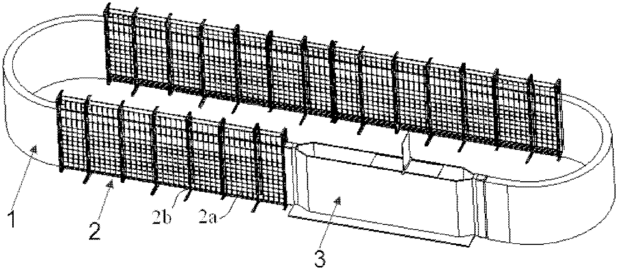
[0044] figure 1 A schematic structural view of a loop reactor according to a first preferred embodiment of the present invention is shown.
[0045] Such as figure 1 As shown, the loop reactor mainly includes a flexible transparent container 1 , a rigid frame 2 and a stirring box 3 . exist figure 1 In , only the rigid frame in the middle part is shown, and the rigid frames at the corners at both ends are removed to show the flexible transparent container 1 .
[0046] The rigid frame 2 constitutes an inner chamber shaped like a circular racetrack and having a rectangular cross-section. The flexible transparent container 1 also forms an annular racetrack shape roughly consistent with the rigid frame 2 and is accommodated in the inner chamber of the rigid frame 2 , and the cross-sectional shape of the flexible transparent container 1 roughly matches the cross-sectional shape of the inner chamber of the rigid frame 2 .
[0047] exist figure 1 In the shown embodiment, when the ...
no. 2 example
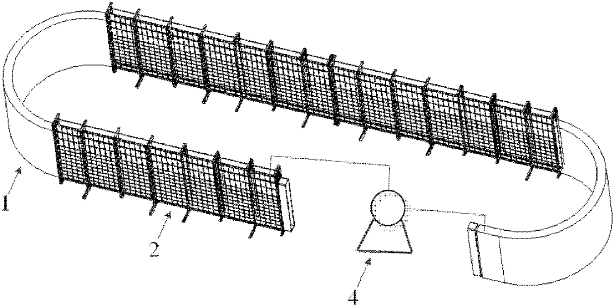
[0070] figure 2 A schematic structural view of a loop reactor according to a second preferred embodiment of the present invention is shown.
[0071] figure 2 The loop reactor of the second preferred embodiment shown with figure 1 The main differences of the loop reactor of the first preferred embodiment shown are: figure 2 The loop reactor of the second preferred embodiment shown is replaced by water pump 4 figure 1 The stirred tank 3 in the loop reactor of the first preferred embodiment is shown.
[0072] Such as figure 2 As shown, the inlet of the water pump 4 communicates with one end of the flexible transparent container 1 , and the outlet communicates with the other end of the flexible transparent container 1 , thereby forming a circulation loop together with the flexible transparent container 1 .
[0073] The following will be based on figure 2 to elaborate figure 2 The installation process of the loop reactor shown:
[0074] 1) Place the rigid frame 2 and ...
no. 3 example
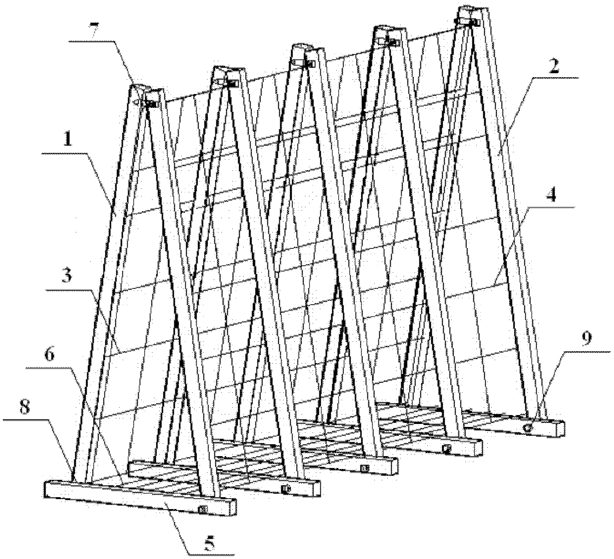
[0082] image 3 A schematic structural view showing the rigid frame 20 of the loop reactor according to the third preferred embodiment of the present invention.
[0083] and figure 1 and figure 2 Compared with the first and second embodiments shown, the image 3 The main differences of the third embodiment shown are: figure 1 and figure 2 The inner cavity of the rigid frame 2 in has a rectangular cross-section, thereby constituting a plate reactor; and image 3 The inner cavity of the rigid frame 20 has a triangular cross-section.
[0084] It should be noted that the cross-sectional shape of the inner cavity of the rigid frame of the present invention is not limited to the illustrated rectangle and triangle, and may also be trapezoidal, circular, regular polygonal or irregular. Meanwhile, in order to match the cross-sectional shape of the inner cavity of the rigid frame, the flexible transparent container should also have a corresponding cross-sectional shape.
[0085...
PUM
 Abstract
Description
Claims
Application Information
 - R&D
- Intellectual Property
- Life Sciences
- Materials
- Tech Scout
- Unparalleled Data Quality
- Higher Quality Content
- 60% Fewer Hallucinations
Browse by: Latest US Patents, China's latest patents, Technical Efficacy Thesaurus, Application Domain, Technology Topic, Popular Technical Reports.
© 2025 PatSnap. All rights reserved.Legal|Privacy policy|Modern Slavery Act Transparency Statement|Sitemap|About US| Contact US: help@patsnap.com