
Sintered magnet motor

A technology of sintered magnets and motors, which is applied in the direction of electric components, magnetic circuit rotating parts, magnetic circuits, etc., can solve the problems of no residual magnetic flux density, no composite magnets, etc. The effect of increased stamina

Inactive Publication Date: 2013-07-03
HITACHI LTD
View PDF7 Cites 10 Cited by
  • Summary
  • Abstract
  • Description
  • Claims
  • Application Information

AI Technical Summary

Problems solved by technology

The high-coercive force magnet is NdFeB magnet, and the low-coercive force magnet is described as an example involving AlNiCo magnet or FeCrCo magnet. variable aspect not documented
[0003] In Patent Document 2, there is a description of a material formed by using fluoride to form a hard magnetic material and a soft magnetic material, but there is nothing about the improvement of magnetic properties due to the soft magnetic material and the combination of the magnetic properties of the soft magnetic material and the hard magnetic material. Control of residual magnetic flux density and description of the process for realizing them
[0004] In Patent Document 3, there is a description about a high-resistance magnet applied to a motor in which fluoride and oxyfluoride are grown in a layered form, and there is also a description about a rotating device using a soft magnetic material and a hard magnetic material formed with fluoride. However, There is no description about the composite magnet material of high saturation remanent magnetic flux density material and hard magnetic material and its effect of improving magnetic characteristics and variable magnetic flux
[0005] Patent Document 4 describes a rotor using a combination of soft magnetic powder and bonded magnets, but there is no description of a composite magnet in which a soft magnetic material is dispersed in a hard magnetic material and sintered

Method used

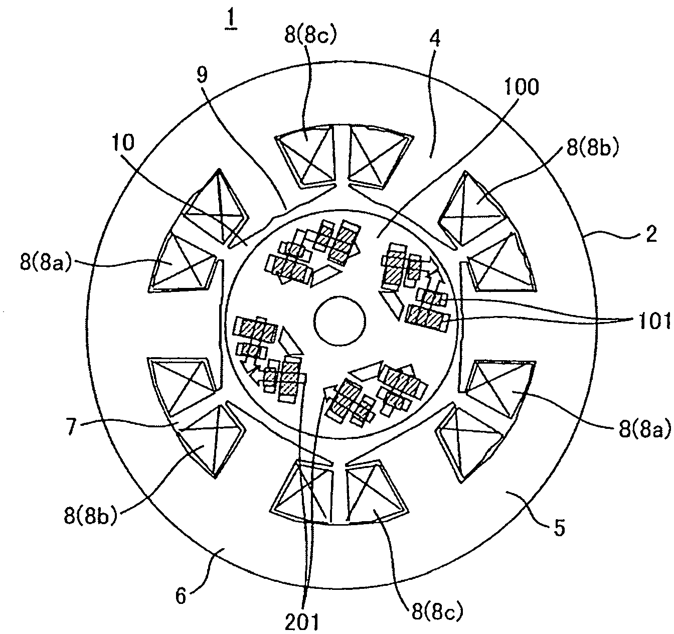
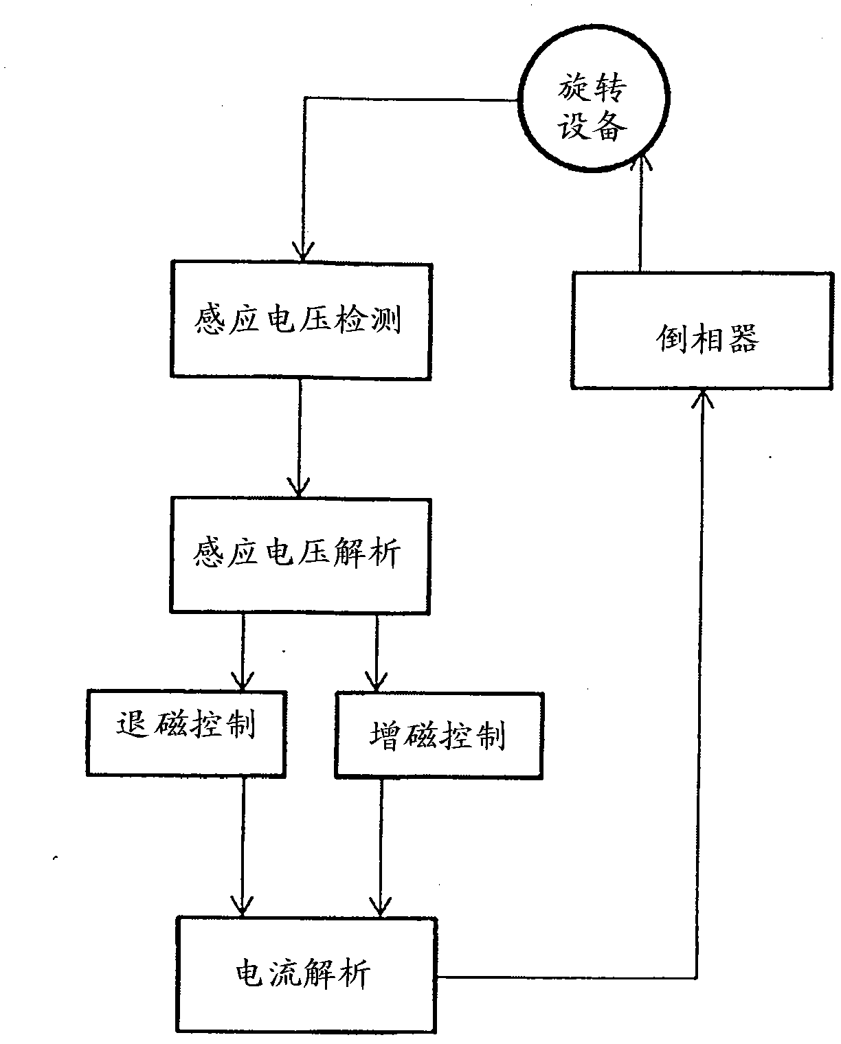

Image

  • Sintered magnet motor
  • Sintered magnet motor
  • Sintered magnet motor

Examples


Embodiment 1

[0048]The Fe-10% Co powder is made by water atomization method, and the average particle size is 10 μm. Contains oxygen near the surface. When the amount of oxygen is 500 ppm or more, fluoride is formed on the surface of the Fe-10%Co powder, and then oxyfluoride grows. This oxyfluoride is represented by RExOyFz (RE is a rare earth element, O is oxygen, F is fluorine, and x, y, and z are positive integers), and contains inevitable elements such as carbon and nitrogen as impurities. Oxyfluoride is formed by coating the surface of water atomized powder with an alcohol solution containing fluoride and oxygen, heating it to 350-900°C, and cooling it rapidly at 10°C / sec.

[0049] After mixing the oxyfluoride-coated atomized powder and the NdFeB-based powder at a mixing ratio of 2:8, after performing magnetic field forming at room temperature (0.5t / cm 2 , 10kOe), and then preformed in a magnetic field above the Curie point of the NdFeB powder. By preforming in a magnetic field at ...

Embodiment 2

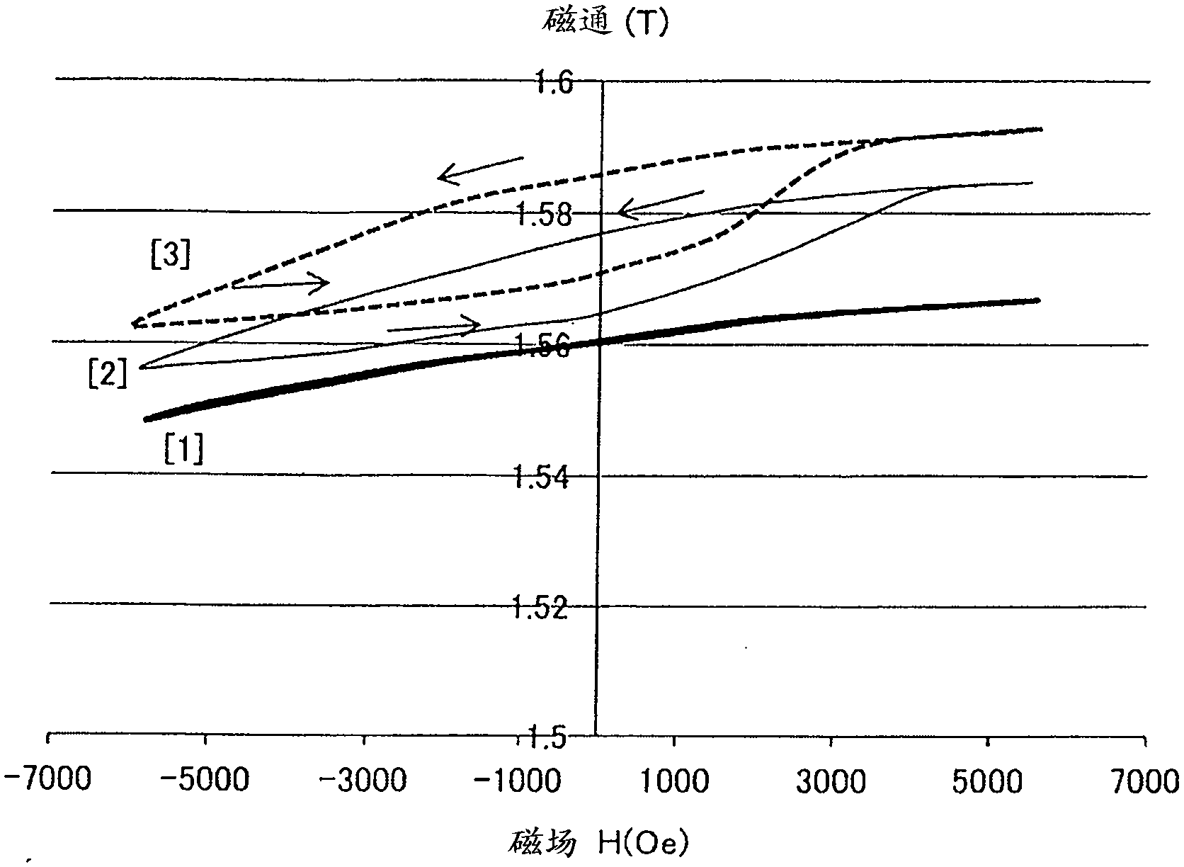
[0064] The sintered magnet of the present example is formed inside with Nd 2 Fe 14 The value of the B-based crystal is larger than that of the Fe-based crystal, and anisotropy is observed in the arrangement of the Fe-based crystal grains. The sintered magnet has the following characteristics: the main phase and only Nd 2 Fe 14 Compared with the sintered magnet of B series crystal, the residual magnetic flux density is higher, and the amount of rare earth elements used is less. image 3 Indicates part of its typical demagnetization curve. image 3 The horizontal axis of is the magnetic field H (Oe), and the vertical axis is the residual magnetic flux density (T).

[0065] [1] is Nd 2 Fe 14 B sintered magnet, [2] is Nd added with 3% FeCo (saturation residual magnetic flux density 1.9T) 2 Fe 14 B / FeCo composite sintered magnet, [3] is Nd with 5% FeCo (saturation residual magnetic flux density 2.0T) added 2 Fe 14 Demagnetization curve of B / FeCo composite sintered magnet....

Embodiment 3

[0073] The Fe-30%Co alloy is a foil-like powder produced by a melt quenching method. The Fe-30%Co alloy high-frequency melted in an inert gas atmosphere was sprayed onto the surface of a copper roll to obtain a plate-shaped or foil-shaped powder with a thickness of 10 μm and an average particle diameter of the major axis of 100 μm. In order to ensure magnetic properties, even if it contains various metal elements and semi-metal elements other than Fe and Co, as long as the content is within 20 atomic%, it can be compared with Nd 2 Fe 14 The saturation magnetization of the B-based crystal is higher, and the maximum energy product after sintering can be larger than that of the case where the FeCo-based alloy is not used.

[0074] Mix Fe-30% Co alloy powder with a saturation remanence flux density of 2.1T and Nd with a saturation remanence flux density of 1.5T at a mixing ratio of 1:9 2 Fe 14 The B-based powder is preformed at room temperature and then preformed at 400°C to ad...


PUM

PropertyMeasurementUnit
particle sizeaaaaaaaaaa
diameteraaaaaaaaaa
diameteraaaaaaaaaa

Abstract

The invention relates to a sintered magnet motor. In conventional technology, there is no example in which the maximum energy product of a Nd2Fe14B sintered magnet is increased and the remanent magnetic flux density is made variable, and it is difficult to provide a variable magnetic flux motor using a sintered magnet of one kind. The sintered magnet motor includes a rotor, a stator, and coils. Sintered magnets are disposed on the rotor. In the sintered magnet motor, a residual magnetic flux density of each of the sintered magnets is controlled by a magnetic field generated by a coil current.

Description

technical field [0001] The present invention relates to a motor using a magnet obtained by sintering a composite material of an Fe-based alloy and a NdFeB-based compound exhibiting a high saturation residual magnetic flux density. Background technique [0002] Patent Document 1 discloses an example of a motor using permanent magnets having different material compositions between high-coercivity magnets and low-coercivity magnets. The high-coercive force magnet is NdFeB magnet, and the low-coercive force magnet is described as an example involving AlNiCo magnet or FeCrCo magnet. Variable aspects are not documented. [0003] In Patent Document 2, there is a description of a material formed by using fluoride to form a hard magnetic material and a soft magnetic material, but there is nothing about the improvement of magnetic properties due to the soft magnetic material and the combination of the magnetic properties of the soft magnetic material and the hard magnetic material. ...

Claims


Application Information

Patent Timeline
Patent Type & Authority Applications(China)
IPC IPC(8): H02K1/22H01F1/057H01F1/08
CPCH02K1/2766H01F41/0293H02K1/02
Inventor 小室又洋日野徳昭佐通祐一
Owner HITACHI LTD
Learn More