
Ways to Extend Ion Source Life

An ion source and ion implanter technology, applied in the field of forming and/or accumulating deposits in ion source components, can solve the problems of reducing tool utilization, large tool downtime, etc., and achieve the effect of improving tool utilization

Active Publication Date: 2018-06-22
PRAXAIR TECH INC
View PDF7 Cites 0 Cited by
  • Summary
  • Abstract
  • Description
  • Claims
  • Application Information

AI Technical Summary

Problems solved by technology

In addition to the cost of cleaning or replacing chamber components, this operation can result in significant tool downtime and reduced tool utilization

Method used


Image

  • Ways to Extend Ion Source Life
  • Ways to Extend Ion Source Life
  • Ways to Extend Ion Source Life

Examples


Embodiment Construction

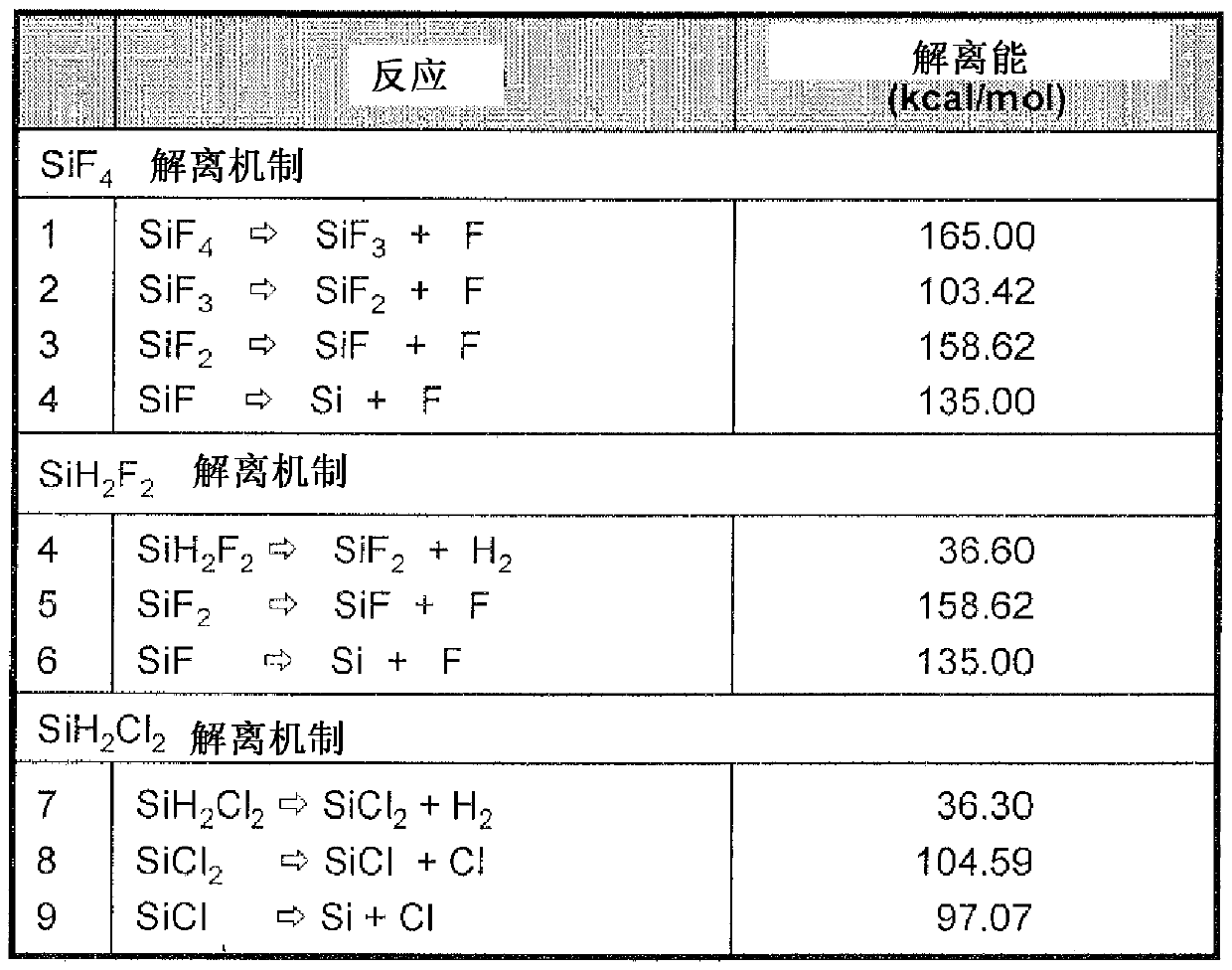
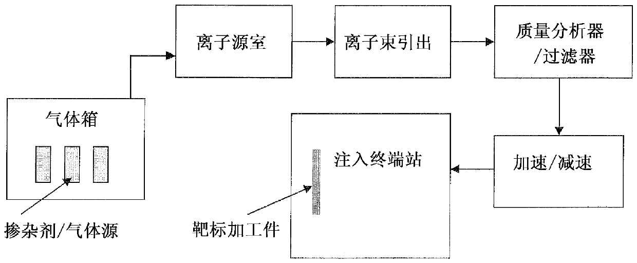
[0026] The invention relates to a method for implanting ions into a workpiece, which method improves or prolongs the ion source life of an ion implanter. Moreover, the method of the present invention provides improved life of the ion implanter source without the accompanying loss of equipment throughput.

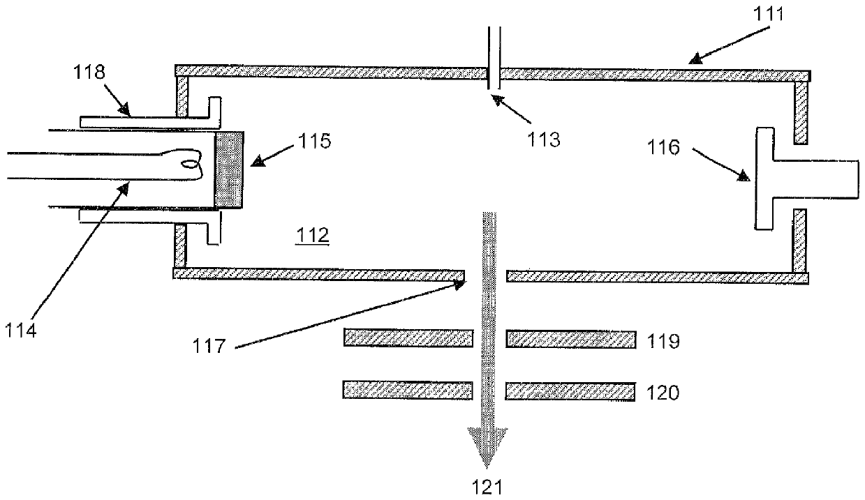
[0027] The present invention can be used to use a heated cathode type ion source (e.g. figure 1 IHC (Indirect Heated Cathode) ion source shown in) to operate the ion implanter. figure 1 The ion source shown in includes an arc chamber wall 111 that defines an arc chamber 112. In the operation of the injection machine, the source gas is introduced into the source chamber. The gas can be introduced into the source chamber through, for example, a gas feed port 113 on the chamber side. The ion source includes a filament 114. The filament is typically a tungsten-containing filament. For example, the filament may contain tungsten or a tungsten alloy containing at least 50% tungst...


PUM


Abstract

The present invention relates, in part, to methods of preventing or reducing the formation and / or accumulation of deposits in ion source components of ion implanters used in semiconductor and microelectronics manufacturing. The ion source assembly includes an ionization chamber and one or more components contained within the ionization chamber. The method involves introducing a dopant gas into the ionization chamber, wherein the dopant gas has a composition sufficient to prevent or reduce the formation of fluoride ions / fluorine radicals during ionization. The dopant gas is then ionized under conditions sufficient to prevent or reduce the formation and / or accumulation of deposits inside the ionization chamber and / or on the one or more components contained within the ionization chamber . The deposits adversely affect the normal operation of the ion implanter, resulting in frequent downtime and reduced tool utilization.

Description

Invention field [0001] The present invention relates in part to methods for preventing or reducing the formation and / or accumulation of deposits in ion source components of ion implanters used in semiconductor and microelectronic manufacturing. The ion source component includes an ionization chamber and one or more components contained in the ionization chamber. The deposits adversely affect the normal operation of the ion implanter, causing frequent downtime and reducing tool utilization. Background of the invention [0002] Ion implantation is an important process in the manufacture of semiconductor / microelectronic devices. An ion implantation process is used in integrated circuit manufacturing to introduce dopant impurities into the semiconductor wafer. The desired dopant impurities are introduced into the semiconductor wafer to form a doped region at a desired depth. The dopant impurities are selected to combine with the semiconductor wafer material to create an electrical...

Claims


Application Information

Patent Timeline
Patent Type & Authority Patents(China)
IPC IPC(8): H01J37/08H01J37/317C23C14/48
CPCH01J37/08H01J37/3171H01J2237/022H01J2237/002
Inventor A.辛哈L.A.布朗
Owner PRAXAIR TECH INC
Learn More