Absorbent for cutting ceramics by aid of fiber laser

A fiber laser and absorber technology, which is applied in laser welding equipment, welding/cutting media/materials, welding media, etc., can solve the problems of inability to cut ceramics at one time and cut light, etc., and achieve the effect of easy cleaning and good light absorption effect

Active Publication Date: 2013-07-10
SUZHOU SUNSHINE LASER & ELECTRONICS TECH CO LTD
View PDF10 Cites 6 Cited by
  • Summary
  • Abstract
  • Description
  • Claims
  • Application Information

AI Technical Summary

Problems solved by technology

[0005] The technical problem solved by the present invention is to provide a new absorber to coat the ceramic surface to ensure the absorption of laser light on the ceramic surface in order to solve the problem that the existing optical fiber laser cutting technology has the phenomenon of cutting off light, which leads to the inability to cut ceramics at one time. Improve cutting efficiency

Method used


Image

  • Absorbent for cutting ceramics by aid of fiber laser
  • Absorbent for cutting ceramics by aid of fiber laser
  • Absorbent for cutting ceramics by aid of fiber laser

Examples


Embodiment 1

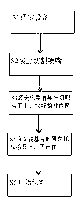
[0017] Embodiment 1, a kind of method for optical fiber laser cutting ceramics, see attached Figure 1-4 , including the following steps:

[0018] S1. Debug the equipment, set the laser frequency, pulse width, speed and focus height and other parameters. The laser frequency is 10kHz, the pulse width is 28ms, the speed is 50mm / s, and the focus height is 20000step, where step is the laser cutting equipment Standard units in the parameter database when adjusting focus height;

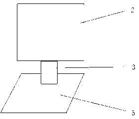
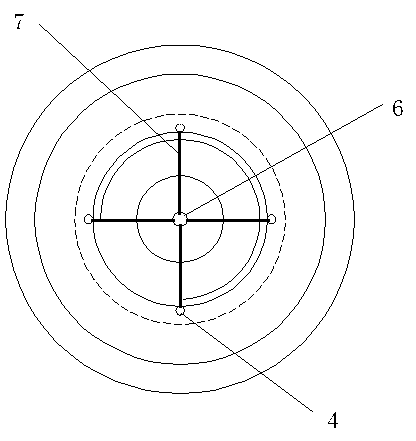
[0019] S2, install the cutting nozzle, the nozzle and the cutting head 2 of the laser equipment are connected by threads, this nozzle is different from the traditional nozzle, it is redesigned, the nozzle is made of copper material, including the nozzle body 3, the air flow channel 1 and the jet hole 6, the nozzle, the jet hole 6 and the air guide hole 4 are all circular, and there are 4 air guide holes 4 and cross grooves 7 on the contact surface 8 of the nozzle, the diameter of the jet hole 6 is 0.8mm, ...

Embodiment 2

[0024] Embodiment 2: It differs from Embodiment 1 in that,

[0025] In step S1, the frequency of the laser is 5 kHz, the pulse width is 10 ms, the speed is 8 mm / s, and the focus height is 18000 steps;

[0026] In step S2, the diameter of the jet hole 6 is 0.7 mm, and the diameter of the air guide hole 4 is 0.5 mm;

[0027] In step S4, the volume ratio of the oily material to acetone is 1:500, the pigment accounts for 10% by mass of the oily material, the pigment auxiliary agent accounts for 10% by mass of the oily material, and the stabilizer accounts for 10% by mass of the oily material 30%, the mass percentage of the resist in the oily material is 30%, the mass percentage of the wetting agent in the oily material is 10%, and the mass percentage of the preservative in the oily material is 10%.

[0028]

Embodiment 3

[0029] Embodiment 3: It differs from Embodiment 1 in that,

[0030] In step S1, the frequency of the laser is 15kHz, the pulse width is 50ms, the speed is 80mm / s, and the focus height is 18000step;

[0031] In step S2, the diameter of the jet hole 6 is 1 mm, and the diameter of the air guide hole 4 is 0.8 mm;

[0032] In step S4, the volume ratio of the oily material to acetone is 1:550, the pigment accounts for 30% by mass of the oily material, the pigment auxiliary agent accounts for 30% by mass of the oily material, and the stabilizer accounts for 30% by mass of the oily material is 10%, the mass percentage of the resist is 10% of the oily material, the wetting agent is 10% of the mass of the oily material, and the preservative is 10% of the mass of the oily material.

[0033]


PUM


Abstract

Disclosed is an absorbent for cutting ceramics by the aid of fiber laser. The absorbent is coated on the surface of a ceramic in a technological process for cutting the ceramic by the aid of the fiber laser. The absorbent is characterized in that an oily material and acetone are proportioned to manufacture the absorbent, and colorants, colorant assistants, stabilizers, resists, wetting agents and preservatives are proportioned to manufacture the oily material. The absorbent has the advantages that a light absorption effect of the ceramic is excellent after the absorbent is used for the ceramic, a phenomenon of light interruption is prevented, the ceramic can be cut by the aid of the laser at one step, the absorbent is environment-friendly, can be easily coated on the surface of the ceramic and is easy to clean, the ceramic can be cleaned in alcohol after being cut, intrinsic characteristics of the ceramic cannot be changed, corrosion is prevented, the appearance of the ceramic is identical to that of a ceramic which is not coated with the absorbent, and the like.

Description

technical field [0001] The invention relates to the field of optical fiber laser cutting ceramics, in particular to an absorbent for optical fiber laser cutting ceramics. Background technique [0002] The laser cutting process uses the energy released when the laser beam irradiates the ceramic surface to melt and evaporate the ceramic. Through the focusing equipment, the laser beam is concentrated in a small area, and the energy is highly concentrated to rapidly and locally heat the cutting part, making the material Evaporation, with the relative linear movement of the beam and the material, the holes are continuously formed into a narrow slit, the cutting edge is little affected by heat, and the laser beam does not exert any force on the material, which is non-contact processing, so laser processed ceramics It has the advantage of small or no deformation. In the current laser cutting ceramic industry, most of them use the traditional carbon dioxide laser cutting ceramic tec...

Claims


Application Information

Patent Timeline
Patent Type & Authority Applications(China)
IPC IPC(8): B23K35/362B23K26/18B05B1/02
Inventor 王华杰王荣
Owner SUZHOU SUNSHINE LASER & ELECTRONICS TECH CO LTD
Why Eureka
Try Eureka