Stator permanent magnetic flux-switching bearing-free motor with U-shaped teeth

A bearingless motor, flux switching technology, applied in the direction of magnetic circuit shape/style/structure, winding conductor shape/style/structure, electrical components, etc., can solve the problems of heat dissipation and mechanical firmness, efficiency, power The factor is not as good as that of permanent magnet motors, and the utilization rate of permanent magnets is reduced, achieving the effects of compact structure, low loss, and high power density

Inactive Publication Date: 2013-07-10
SOUTHEAST UNIV
View PDF6 Cites 20 Cited by
  • Summary
  • Abstract
  • Description
  • Claims
  • Application Information

AI Technical Summary

Problems solved by technology

However, the existing bearingless permanent magnet synchronous motors with traditional rotor permanent magnet structure have certain limitations: on the one hand, the permanent magnets mounted on the rotor surface or embedded in the rotor destroy the overall structure of the rotor, while as For high-speed motors, the rotors are usually in a high-speed or even ultra-high-speed operating state (tens of thousands of revolutions per minute or even hundreds of thousands of revolutions per minute). Fixing devices made of stainless steel or metal fiber materials lead to complex structures, increased manufacturing costs, long equivalent air gaps, and reduced utilization of permanent magnets; As the temperature rises, the performance of the permanent magnet mainly compose

Method used


Image

  • Stator permanent magnetic flux-switching bearing-free motor with U-shaped teeth
  • Stator permanent magnetic flux-switching bearing-free motor with U-shaped teeth

Examples


Embodiment Construction

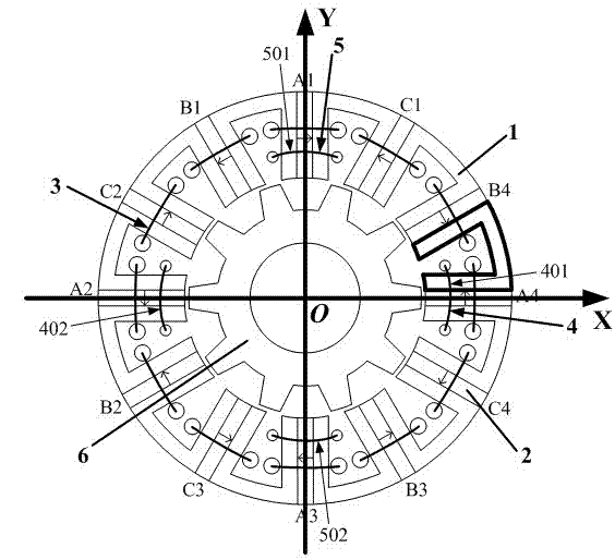
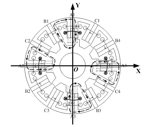
[0028] Taking a three-phase stator 12-pole / rotor 10-pole stator permanent magnet flux switching bearingless motor as an example, its cross-sectional view is as follows figure 1 The schematic diagram of the structure of the stator permanent magnet flux switching bearingless motor shown includes the stator 1 and the rotor 6, the rotor 6 is located inside or outside the stator 1, both the stator 1 and the rotor 6 are salient pole structures, and the stator 1 is provided with three Relatively symmetrical centralized armature winding 3 , X-axis suspension winding 4 , Y-axis suspension winding 5 and permanent magnet 2 . There are 12 evenly distributed poles on the stator 1, and 10 evenly distributed poles on the rotor 6; the stator core is composed of 12 "U"-shaped conductive core units (such as figure 1 As shown in the part drawn by the middle thick black line, since the flux switching motor itself is a new type of motor, its stator structure is usually composed of a "U"-shaped per...


PUM


Abstract

The invention relates to a stator permanent magnetic flux-switching bearing-free motor with U-shaped teeth. The stator permanent magnetic flux-switching bearing-free motor with the U-shaped teeth is simple in structure, fastened in rotor and high in power, efficiency and reliability. The stator permanent magnetic flux-switching bearing-free motor with the U-shaped teeth comprises a stator and a rotor. The rotor is arranged inside or outside the stator. The rotor and the stator are of doubly-salient structures. Multiple-phase armature windings which are symmetrically arranged, floating windings which respectively control an X axis direction and a Y axis direction and a permanent magnet are arranged on the stator. The armature windings and the floating windings are composed of concentrated coils. Each coil spans in grooves of two sides of a stator iron core unit which is composed of two U-shaped permeance iron cores and a permanent magnet in between. The floating windings are only wound on the stator iron core unit wound by a coil of an A-phase armature winding. According to the stator permanent magnetic flux-switching bearing-free motor with the U-shaped teeth, based on advantages of a traditional flux-switching permanent magnetic motor, the stator permanent magnetic flux-switching bearing-free motor is simple in structure like a bearing-free switch reluctance motor and has high efficiency and high power density like a bearing-free rotor permanent magnetic motor and high theoretic and practical value.

Description

technical field [0001] The invention is a stator permanent magnet bearingless motor with simple structure, firm rotor, high reliability and high efficiency, which is especially suitable for high-speed operation, and belongs to the technical field of motor manufacturing. Background technique [0002] In the fields of high-speed drive, sealed transmission and aerospace, there is an urgent need for the bearingless operation technology of the motor. Due to the many limitations of mechanical bearings, ordinary motors cannot meet the requirements of long-term high-speed operation; the control equipment of air-floating and liquid-floating bearings is relatively large and the cost is high; magnetic suspension bearings have no mechanical wear, no lubrication and sealing systems, and strong environmental adaptability, etc. However, the overall structure of the magnetic bearing motor system is relatively complex, the power density is not high, and the critical speed and power capacity ...

Claims


Application Information

Patent Timeline
IPC IPC(8): H02K1/17H02K1/16H02K3/28H02K3/46
Inventor 花为邵凌云程明
Owner SOUTHEAST UNIV
Why Eureka
Try Eureka