Power system sub-synchronous oscillation mode identification method

A technology of subsynchronous oscillation and mode identification, applied in the direction of reducing/preventing power oscillation, etc., can solve the problem that it is difficult to effectively identify the subsynchronous oscillation mode of the power system, the wavelet analysis method is difficult to distinguish similar frequency components, and it is difficult to extract the torsional vibration mode. In order to enhance the global detection ability, improve the local development ability, improve the simplicity and flexibility

Active Publication Date: 2013-07-17
WUHAN UNIV
View PDF2 Cites 34 Cited by
  • Summary
  • Abstract
  • Description
  • Claims
  • Application Information

AI Technical Summary

Problems solved by technology

Zheng Rui et al [1] Combining the time domain simulation method and Prony analysis method, the modal characteristics of subsynchronous oscillation were studied, and the modes that may cause subsynchronous oscillation of the system were obtained. However, the Prony identification and fitting results are sensitive to noise, and it is difficult to select the model order
Huang Jiading and others [2] Using wavelet filtering and Hilbert-Huang transform can extract parameters such as the instantaneous frequency, instantaneous amplitude, and phase of each component of the subsynchronous resonance of the system, but the HHT method requires too high a sampling rate
Deng Jixiang and others [3] The method of combining empirical mode decomposition (EMD) and continuous Morlet wavelet transform to analyze and detect the system response curve can detect the dominant low-frequency oscillation mode of the system, but the wavelet analysis method is difficult to distinguish similar frequency components, and it is difficult to extract torsion Vibration mode damping parameters
In addition, although some existing subsynchronous oscillation mode identification methods based on measured data can extract the modal parameters, they cannot adaptively locate the disturbance period according to the characteristics of each oscillation mode. The time-varying characteristics of the oscillation mode require Extraction of follow-up work
Therefore, it is difficult for the existing technology to effectively identify the subsynchronous oscillation mode of the power system

Method used


Image

  • Power system sub-synchronous oscillation mode identification method
  • Power system sub-synchronous oscillation mode identification method
  • Power system sub-synchronous oscillation mode identification method

Examples


specific Embodiment approach

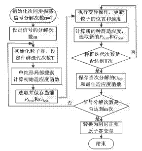
[0095] The following will combine figure 1 The specific embodiment of the present invention is described in detail, including steps:

[0096] Step 1: Construct the atomic library of the subsynchronous oscillation signal to be identified with the modal parameters of the subsynchronous oscillation signal as the atomic index, and initialize the particle swarm based on the atomic library of the subsynchronous oscillation signal; the atomic library of the subsynchronous oscillation signal is a damped sine Quantitative atom model, the atomic index in this model γ=(F, φ, ρ, t s ,t e ), where F is the atomic frequency, φ is the phase, ρ is the atomic damping coefficient, t s with t e are the start and end moments of the damped sinusoidal atoms, respectively.

[0097] Step 2, set the total number of signal decomposition m=20, and initialize the subsynchronous oscillation signal decomposition number n=1; set the total number of particle swarm decomposition iterations T=60 according ...

Embodiment 1

[0117] In this embodiment, the method of the present invention is specifically described by taking the oscillation test signal with time-varying frequency as an example, including steps:

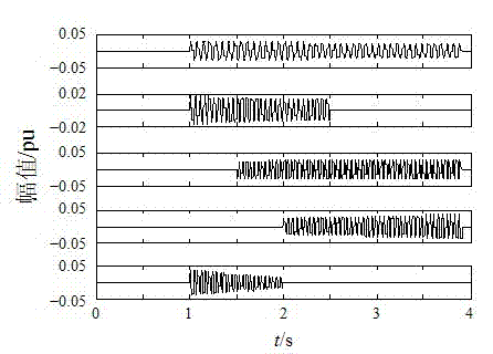
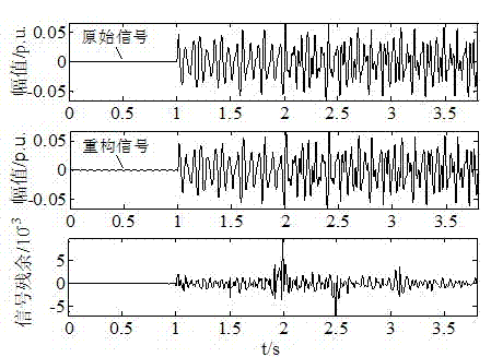
[0118] Step 1. Construct an oscillation test signal with time-varying frequency. The test signal is composed of five modes. The expression of the signal s(t) is as follows:

[0119] s ( t ) = 6 e - 0.08 t sin ( 30 πt ) , 1 ≤ t ≤ 3.9 s ...

Embodiment 2

[0141] This embodiment takes Figure 6 The method of the present invention is specifically described by taking the IEEE first standard model as an example.

[0142] See Figure 6 In the IEEE first standard model, the generator shaft system adopts a six-mass spring model, and the series compensation degree is 66.21%. There are five torsional vibration modes in this model, and the torsional vibration frequencies are 15.71Hz, 20.21Hz, 25.55Hz, 32.28Hz and 47.45Hz.

[0143] In order to extract the subsynchronous oscillation mode related to the torsional vibration strength of the mass, this embodiment selects the generator speed deviation Δω as the analysis signal. At the moment of 1.5s, the system has a three-phase short circuit at node B through the transition impedance, and the fault duration is 0.075s. The Δω waveform of the period from 0 to 12s is recorded, and the sampling frequency is 1kHz.

[0144] The Δω waveform of the disturbance is a nonlinear and non-stationary oscill...


PUM


Abstract

The invention discloses a power system sub-synchronous oscillation mode identification method which is characterized in that time complexity of the matching pursuit search process is reduced by aid of a particle swarm optimization, sub-synchronous oscillation signals are subjected to atomic decomposition in an optimized matching pursuit method, and atomic parameters are converted to sub-synchronous oscillation mode parameters after the optimum atom is searched. The power system sub-synchronous oscillation mode identification method can accurately identify power system sub-synchronous oscillation mode parameters, has good time-frequency characteristic, is favorable for deeply analyzing power system sub-synchronous oscillation characteristic, accordingly effectively restrains oscillation, and ensures stable operation of a unit and a power system.

Description

technical field [0001] The invention relates to safe and stable operation of a power system, and more particularly to a method for identifying a subsynchronous oscillation mode of a power system. Background technique [0002] With the gradual formation of the AC-DC interconnection pattern of my country's power grid, a large number of non-linear devices such as HVDC (High Voltage Direct Current Transmission System) and FACTS (Flexible AC Transmission System) have been added to the power system, and the problem of subsynchronous oscillation in the power system has become increasingly prominent. Subsynchronous oscillation belongs to the oscillation instability of the system, which is caused by a special electromechanical coupling in the power system, which will lead to torsional vibration instability of the generator shaft system and even damage to the shaft system, seriously threatening the safe operation of the power system. Accurately identifying the characteristic parameter...

Claims


Application Information

Patent Timeline
Patent Type & Authority Applications(China)
IPC IPC(8): H02J3/24
Inventor 刘涤尘董飞飞廖清芬唐飞宫璇孙文涛赵洁冀星沛
Owner WUHAN UNIV
Why Eureka
Try Eureka