
A kind of numerical control cutting tool with craltin superlattice coating and preparation method thereof

A superlattice and cutting tool technology, applied in lathe cutting tools, coating, metal material coating technology, etc., can solve the problems that cannot meet the requirements of high-quality processed parts, high friction coefficient, poor wear resistance, etc. , to achieve the effects of improved friction coefficient and structural thermal stability, high toughness, and excellent adhesion

Active Publication Date: 2016-04-13
重庆市硅酸盐研究所有限责任公司
View PDF6 Cites 0 Cited by
  • Summary
  • Abstract
  • Description
  • Claims
  • Application Information

AI Technical Summary

Problems solved by technology

Currently widely used industrial hard coatings include TiN, CrN, GiC and TiAlN, etc. Although these materials have significantly improved the life of CNC tools and the quality of processed parts, because the coating structure is basically columnar crystal or developed columnar crystal structure, although the hardness of the coating is high, but the wear resistance is poor, the friction coefficient is high, and it is increasingly unable to meet the needs of high-quality processed parts

Method used

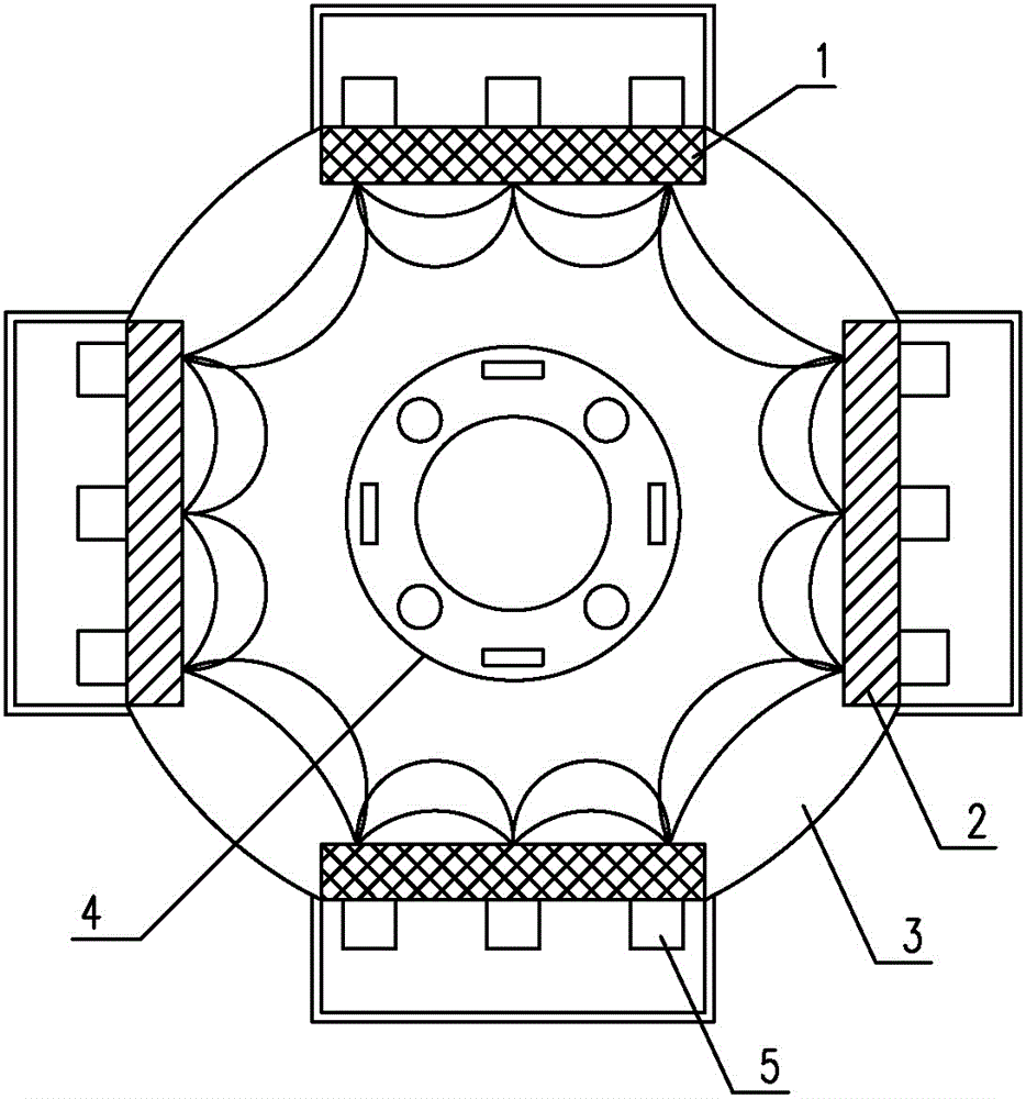

Image

  • A kind of numerical control cutting tool with craltin superlattice coating and preparation method thereof
  • A kind of numerical control cutting tool with craltin superlattice coating and preparation method thereof
  • A kind of numerical control cutting tool with craltin superlattice coating and preparation method thereof

Examples


Embodiment 1

[0036] First, clean the prepared cemented carbide tool, clamp it on the sample holder, and start vacuuming. When the background vacuum is lower than 1.0×10 -3 At Pa, start heating, the temperature stabilizes at 300℃, the sample holder speed stabilizes at 4 rpm, Ar gas is introduced, and the water cooling device of the cathode target is turned on to start cooling, and the four cathode targets and the bias power supply are turned on at the same time. Keep the target power turned on at the lowest level, keep the bias voltage at 500V, and sputter cleaning for 30 minutes; after the glow cleaning, gradually reduce the substrate bias voltage to 100V, the element Ti target gradually increases the power, and the two alloy targets remain at the lowest power state . To deposit the metal Ti adhesion layer; after finishing this work, adjust the Ti target power, this target is the spectrum control target, after the spectrum control is turned on, the power is no longer adjusted, turn on the sp...

Embodiment 2

[0038] First, clean the prepared WC8Co series cemented carbide tool, clamp it on the sample holder, and start vacuuming. When the background vacuum is lower than 1.0×10 -3 At Pa, start heating, the temperature stabilizes at 350℃, the sample holder speed stabilizes at 3 rpm, Ar gas is introduced, and the water cooling device of the cathode target is turned on to start cooling, and the four cathode targets and the bias power supply are turned on at the same time. Keep the target power turned on at the lowest level, keep the bias voltage at 500V, and sputter cleaning for 30 minutes; after the glow cleaning, gradually reduce the substrate bias voltage to 100V, the element Ti target gradually increases the power, and the two alloy targets remain at the lowest power state . To deposit the metal Ti adhesion layer; after finishing this work, adjust the Ti target power, this target is the spectrum control target, after the spectrum control is turned on, the power is no longer adjusted, t...


PUM

PropertyMeasurementUnit
thicknessaaaaaaaaaa
thicknessaaaaaaaaaa
thicknessaaaaaaaaaa

Abstract

The invention belongs to the technical field of thin-film materials, in particular to a numerical control cutting tool with a CrAlTiN superlattice coating and a manufacturing method thereof. The numerical control cutting tool with the CrAlTiN superlattice coating comprises an ultra-fine grain hard alloy cutter body, wherein the CrAlTiN superlattice coating is deposited on the outer surface of the cutter body, and comprises an adhesive layer, a support layer and a wearing layer from the inside to outside; the adhesive layer is a Ti metal layer; the support layer is a TiN layer; the wearing layer is a nitride multilayer which is formed by an alternately-arranged CrAlN layers and TiN layers; and the nitride multilayer is of a polycrystalline superlattice structure. With the adoption of the numerical control cutting tool with the CrAlTiN superlattice coating and the manufacturing method thereof, the problems that the wear-resisting property of a numerical control cutting tool is poor, and the friction coefficient is higher in the prior art are solved; and the numerical control cutting tool with the CrAlTiN superlattice coating has the advantages of being higher in hardness, better in wear-resisting property, and lower in friction coefficient; and with the adoption of the numerical control cutting tool with the CrAlTiN superlattice coating, the service life of the cutting tool can be obviously improved, and the surface quality of a processed component is improved.

Description

Technical field [0001] The invention belongs to the technical field of thin film materials, in particular to a numerical control tool with a CRALTIN ​​superlattice coating and a preparation method thereof. Background technique [0002] A machine tool is a machine that processes metal blanks into machine parts. It is a machine that makes machines. It is customarily referred to as a machine tool. In modern machinery manufacturing, all parts that require high precision and finer surface roughness must be cut on the machine tool for final processing. In general machine manufacturing, the machining workload undertaken by machine tools accounts for 40%-60% of the total machine manufacturing workload. Machine tools play a major role in the modernization of the national economy. Therefore, a country's machine tools, especially modern CNC machine tools, have become a symbol of a country's manufacturing industry. With the development and application of new technologies, the manufacturing...

Claims


Application Information

Patent Timeline
Patent Type & Authority Patents(China)
IPC IPC(8): B23B27/14B23P15/28C23C14/35C23C14/06
Inventor 周天勇石永敬王联蒋显全潘复生
Owner 重庆市硅酸盐研究所有限责任公司
Learn More