Test method for wideband radiated immunity test device of on-board display
What is Al technical title?
Al technical title is built by PatSnap Al team. It summarizes the technical point description of the patent document.
A vehicle-mounted display, radiation immunity technology, applied in the direction of measuring devices, instruments, measuring electronics, etc., can solve the problems of low working efficiency in the testing process, the inability to meet the requirements of high-working frequency sample testing, and the impact on physical health, etc., to achieve The effect of saving equipment cost, ensuring safety and improving technical level
Inactive Publication Date: 2015-09-02
FUJIAN INSPECTION & RES INST FOR PROD QUALITY
View PDF4 Cites 0 Cited by
Summary
Abstract
Description
Claims
Application Information
AI Technical Summary
This helps you quickly interpret patents by identifying the three key elements:
Problems solved by technology
Method used
Benefits of technology
Problems solved by technology
As a vehicle-mounted electronic product, the vehicle-mounted display has stricter requirements on immunity to interference, and the test frequency range required for the test is getting wider and wider. However, the current single test instrument is often unable to meet the requirements of high-frequency sample testing due to frequency band limitations. If every To test a certain frequency range, it is necessary to replace the test instrument, and the work efficiency of the whole test process is very low.
In addition, at present, the judgment of the working status of the tested samples during the radiation resistance test of the vehicle-mounted display is based on the observation of the inspectors, but the impact of high-field electromagnetic radiation interference sources on the health of the experimenters is obvious.
Method used
Image
Click on the blue label to locate the original text in one second.
Reading with bidirectional positioning of images and text.
Examples
Embodiment Construction
[0017] The present invention will be further described below through the specific embodiments of the accompanying drawings. (but not limitation of the invention).
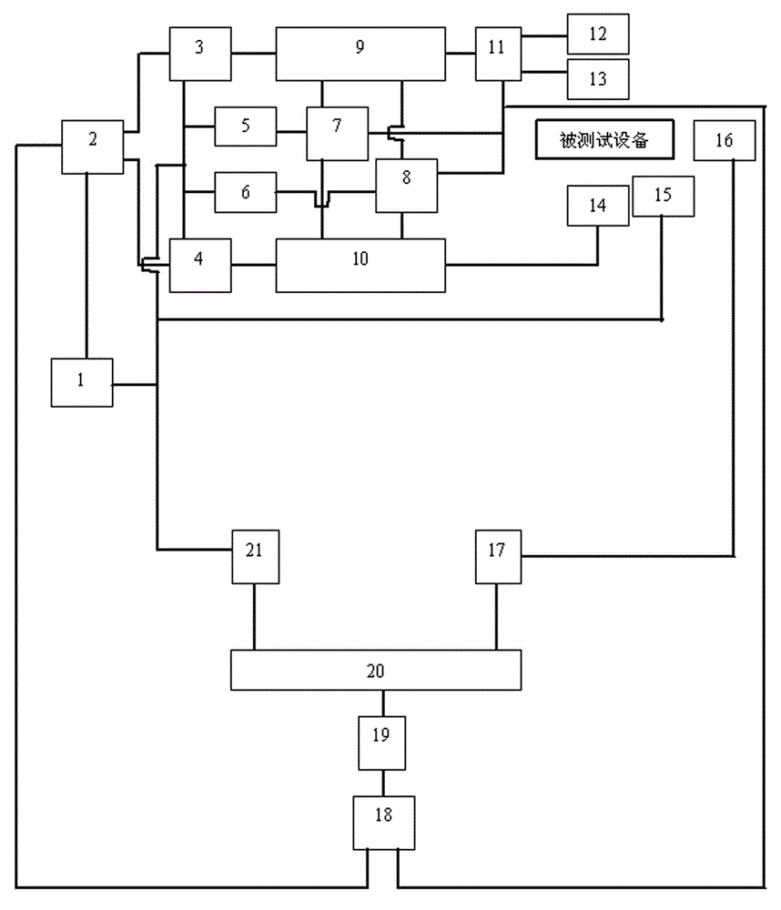
[0018] Such as figure 1 As shown, the vehicle-mounted display broadband radiation immunity test device of the present invention is provided with radio frequency interference signal source 1, the first coaxial radio frequency switch 2, low-band power amplifier 3, high-band power amplifier 4, forward power meter 5, Backward power meter 6, second coaxial radio frequency switch 7, third coaxial radio frequency switch 8, first directional coupler 9, second directional coupler 10, fourth coaxial radio frequency switch 11, 20MHz-200MHz low frequency dual Cone antenna 12, logarithmic antenna 13, horn antenna 14, field strength meter 15, camera 16, high-speed image acquisition card 17, radio frequency switch control module 18, serial port expansion card 19, control host 20, GPIB interface card 21 and vehicle display 22 , ...
PUM
Abstract
The invention discloses a test device and a test method for broadband radiated immunity of a vehicle display device as well as application. The test device is provided with a radio frequency interference signal source, a first coaxial radio frequency switch, a low-frequency section power amplifier, a high-frequency section power amplifier, a forward power meter, a backward power meter, a second coaxial radio frequency switch, a third coaxial radio frequency switch, a first oriented coupler, a second oriented coupler, a fourth coaxial radio frequency switch, a 20MHz-200MHz low-frequency bi-conical antenna, a log antenna, a horn antenna, a field strength meter, a camera, a high-speed image acquisition card, a radio frequency switch control module, a serial port expansion card, a control host machine, a GPIB (general purpose interface bus) interface card and the vehicle display device. During testing, a broadband radio frequency interference signal is generated by a radio frequency interference signal source, the control host machine is used for judging the frequency section of the frequency of the interference signal, on the basis of the frequency section, the control host machine is used for controlling the radio frequency switch control module to automatically switch the coaxial radio frequency switches, so that the radio frequency signal source is enabled to be connected with the corresponding power amplifier and the corresponding antenna, and the forward power meter, the backward power meter and a video monitoring device are respectively used for the online monitoring of the testing field strength and the working state of tested equipment.
Description
technical field [0001] The invention relates to a test method of a wide-band radiation immunity test device for a vehicle display. Background technique [0002] Radio frequency electromagnetic field radiation immunity is used to investigate the degree to which the performance of the tested sample is affected when it receives external space radiation disturbance. It is one of the most important test methods in the immunity test of electronic information products. As a vehicle-mounted electronic product, the vehicle-mounted display has stricter requirements on immunity to interference, and the test frequency range required for the test is getting wider and wider. However, the current single test instrument is often unable to meet the requirements of high-frequency sample testing due to frequency band limitations. If every To test a certain frequency range, the test instrument needs to be replaced, and the efficiency of the whole test process is very low. In addition, the dete...
Claims
Application Information
Patent Timeline
Application Date:The date an application was filed.
Publication Date:The date a patent or application was officially published.
First Publication Date:The earliest publication date of a patent with the same application number.
Issue Date:Publication date of the patent grant document.
PCT Entry Date:The Entry date of PCT National Phase.
Estimated Expiry Date:The statutory expiry date of a patent right according to the Patent Law, and it is the longest term of protection that the patent right can achieve without the termination of the patent right due to other reasons(Term extension factor has been taken into account ).
Invalid Date:Actual expiry date is based on effective date or publication date of legal transaction data of invalid patent.
Patent Type & Authority Patents(China)
IPC IPC(8): G01R31/00
Inventor 才辉阮星蔡庆荣林弘钟华彧
Owner FUJIAN INSPECTION & RES INST FOR PROD QUALITY