Pole-changing control permanent magnet synchronous motor

A permanent magnet synchronous motor, pole-changing speed regulation technology, applied in the direction of magnetic circuit rotating parts, magnetic circuit shape/style/structure, etc., can solve the problem of increasing armature current, limiting the application range of permanent magnet synchronous motor, rotor magnetic pole It is difficult to change the number of polar pole pairs to achieve the effect of reducing loss, realizing high-speed constant power characteristics, and widening the speed regulation range

Inactive Publication Date: 2013-07-24
HARBIN INST OF TECH
View PDF4 Cites 15 Cited by
  • Summary
  • Abstract
  • Description
  • Claims
  • Application Information

AI Technical Summary

Problems solved by technology

It can be seen that two methods can be used to change the speed of the motor: one is frequency conversion speed regulation, which changes the speed of the motor by changing the frequency of the motor power supply. This is an ideal speed regulation method for AC synchronous motors. However, due to the permanent magnet Synchronous motors are usually excited by high-performance rare-earth permanent magnets, which make it difficult to adjust the magnetic field
In the constant power operation area above the base speed, as the speed increases, the back electromotive force of the winding gradually increases. Due to the limitation of the supply voltage and the saturation effect of the current controller, the m

Method used


Image

  • Pole-changing control permanent magnet synchronous motor
  • Pole-changing control permanent magnet synchronous motor
  • Pole-changing control permanent magnet synchronous motor

Examples


specific Embodiment approach 1

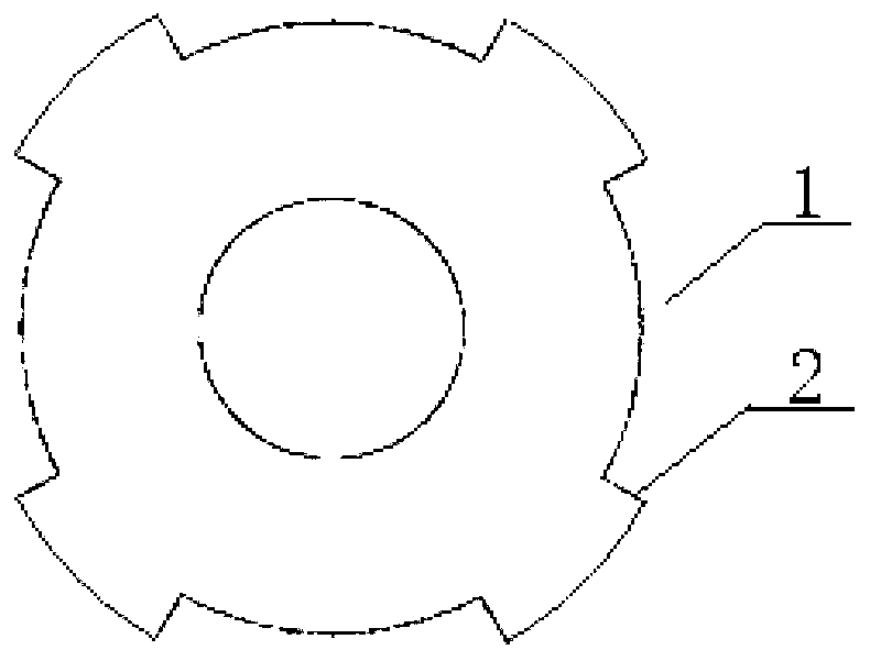
[0018] Specific implementation mode one: see figure 2 , 3 and 4 describe this embodiment. In this embodiment, the pole-changing speed-regulating permanent magnet synchronous motor includes a stator and a rotor, and an air gap is formed between the stator and the rotor; the stator includes a stator core and a stator winding, and the rotor includes a rotor core and a plurality of permanent magnets, and the permanent magnets are tile shape, the multi-piece permanent magnets are divided into two types: strong magnetic permanent magnet 4 and weak magnetic permanent magnet 3; the rotor core is cylindrical, and the air gap side surface of the rotor core has 4 salient poles 2 and 4 grooves 1 structure arranged alternately along the circumferential direction, the cross section of the groove 1 is fan-shaped, the width of each groove 1 along the circumferential direction is twice the width of the salient pole 2 along the circumferential direction, in each groove 1 Embed two tile-shape...

specific Embodiment approach 2

[0019] Specific implementation mode two: see Figure 5 This embodiment will be described. The pole-changing speed-regulating permanent magnet synchronous motor described in this embodiment includes a stator and a rotor, and there is an air gap between the stator and the rotor; the stator includes a stator core and a stator winding, and the rotor includes a rotor core and a plurality of permanent magnets. The permanent magnets are tile-shaped, and the multi-piece permanent magnets are divided into two types: strong magnetic permanent magnets 4 and weak magnetic permanent magnets 3; the rotor core is cylindrical, and the air gap side surface of the rotor core is four salient poles 2 and 4 A structure in which four grooves 1 are arranged alternately along the circumferential direction, the cross section of the grooves 1 is fan-shaped, there are 2 wide grooves and 2 narrow grooves in the 4 grooves 1, and the wide grooves and narrow grooves are alternated Arranged, the width of th...

specific Embodiment approach 3

[0020] Specific implementation mode three: see Figure 6 This embodiment will be described. The pole-changing speed-regulating permanent magnet synchronous motor described in this embodiment includes a stator and a rotor, and there is an air gap between the stator and the rotor; the stator includes a stator core and a stator winding, and the rotor includes a rotor core and a plurality of permanent magnets. The permanent magnet is in the shape of a flat plate, and the multi-piece permanent magnets are divided into two types: strong magnetic permanent magnet 4 and weak magnetic permanent magnet 3; the rotor core is cylindrical, and 12 pieces are axially opened inside the rotor core near the side surface of the air gap. Trapezoidal grooves, the 12 trapezoidal grooves are evenly distributed along the circumferential direction, a permanent magnet is embedded in each trapezoidal groove, and every two strong magnetic permanent magnets 4 and a weak magnetic permanent magnet 3 are arra...


PUM


Abstract

The invention discloses a pole-changing control permanent magnet synchronous motor, relating to a pole-changing control permanent magnet synchronous motor system and belonging to the field of motors. The synchronous motor is characterized in that permanent magnets of a rotor (secondary) are divided into strong-magnetism permanent magnets and weak-magnetism permanent magnets, wherein the weak-magnetism permanent magnets are not magnetized before the operation of the motor, magnet limbs and grooves at/in the surface of the air gap side of the rotor (secondary) are alternatively arrayed along the directions of relative motions of the rotor (secondary) and a stator (primary), the strong-magnetism permanent magnets and the weak-magnetism permanent magnets are alternatively arrayed along the directions of relative motions of the rotor (secondary) and the stator (primary) according to a certain rule; and the strong-magnetism permanent magnets are embedded into the grooves, and the weak-magnetism permanent magnets are fixed on the surfaces of the magnet limbs. According to the pole-changing control permanent magnet synchronous motor, in an application process, the polarity of the magnetic field of the rotor (secondary) can be controlled according to a direct-axis component of the current of the stator (primary), the changing of the number of poles of the main magnetic field of the motor is realized, and furthermore, and the torque (push force) in low speed of the motor and the efficiency in high speed of the motor are improved, so that the speed adjustable range of the motor is broadened.

Description

technical field [0001] The invention relates to a pole-changing speed-regulating permanent magnet synchronous motor system, which belongs to the field of motors. Background technique [0002] With the development of rare earth permanent magnet material technology and permanent magnet motor technology, in recent years, permanent magnet synchronous motors with the advantages of small size, light weight, high efficiency, high power factor, and good control characteristics have been deeply studied and widely used. With the improvement of frequency conversion technology, permanent magnet synchronous motor and frequency conversion control have realized mechatronics, which makes the advantages of permanent magnet synchronous motor drive system more and more obvious. The synchronous motor uses high-performance rare earth permanent magnets to generate the main pole magnetic field, which can greatly improve the operating efficiency and power factor of the motor, and the system has hig...

Claims


Application Information

Patent Timeline
IPC IPC(8): H02K1/27H02K1/24
Inventor 寇宝泉曹海川杨小宝屈娅茹王立强
Owner HARBIN INST OF TECH
Why Eureka
Try Eureka