Axis static state vacuum partition method of integrated rotary transformer

A rotary transformer and vacuum isolation technology, which is applied in the direction of AC/AC converters, electrical components, electromechanical devices, etc., can solve the problem of vacuum isolation between the motor and the displacement measuring device, the narrow distance between the rotary transformer and other parts, the design, Manufacture and maintenance difficulties, etc., achieve the effect of saving development cycle, dynamic error control, and compact structure

Active Publication Date: 2013-07-24
SHANGHAI JIAO TONG UNIV
View PDF3 Cites 12 Cited by
  • Summary
  • Abstract
  • Description
  • Claims
  • Application Information

AI Technical Summary

Problems solved by technology

However, this sealing method is difficult to achieve a high degree of vacuum, and the magnetic fluid is easy to evaporate in a vacuum environment, which is greatly affected by the ambient temperature and the reliability is limited.
Compared with the dynamic sealing isolation method, the static sealing technology can obtain higher vacuum degree and reliability, and can work in a relatively harsh environment. Generally, the static sealing can be realized through a magnetic coupling, but there are also the following disadvantages: the bearing is in the In a vacuum environment, special lubrication methods are required to reduce the pollution of the vacuum environment by particles; in a vacuum environment, permanent magnets and adhesives will cause certain gas leakage; motor stator and rotor, magnetic coupling active ...

Method used


Image

  • Axis static state vacuum partition method of integrated rotary transformer
  • Axis static state vacuum partition method of integrated rotary transformer
  • Axis static state vacuum partition method of integrated rotary transformer

Examples


Embodiment Construction

[0042] The present invention will be described in detail below in conjunction with specific embodiments. The following examples will help those skilled in the art to further understand the present invention, but do not limit the present invention in any form. It should be noted that those skilled in the art can make several modifications and improvements without departing from the concept of the present invention. These all belong to the protection scope of the present invention.

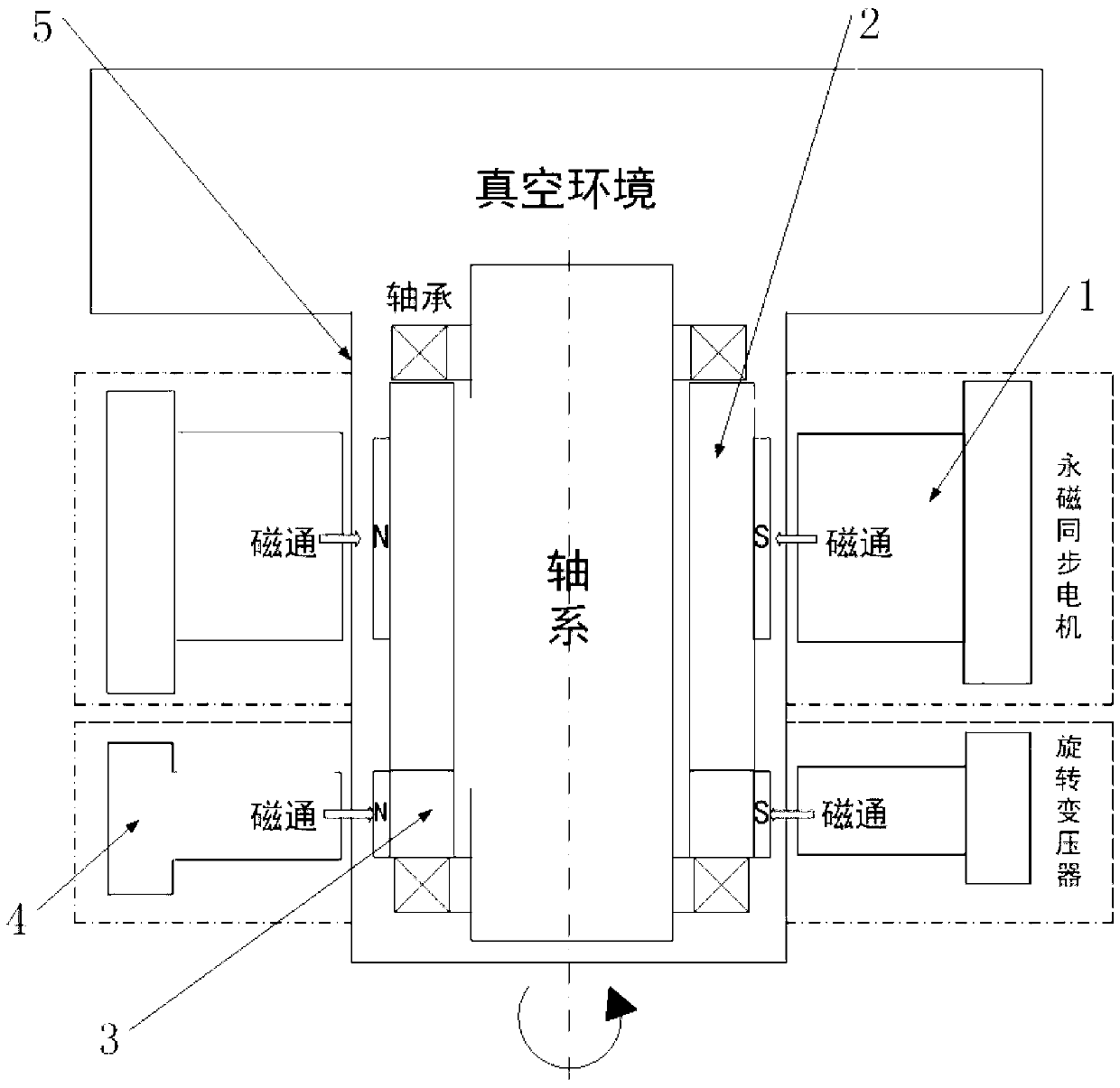
[0043] Such as figure 1 As shown, the method provided by the present invention is applied to the shafting device of a vacuum robot, and the device is mainly composed of a driving part, a position detecting part and a sealing part. Among them: a large-gap permanent magnet synchronous motor with magnetic direct drive technology is designed as the driving component; a sin-cosine reluctance resolver is designed as the position detection component of the shaft system, and an isolation sealing sleeve is...


PUM


Abstract

The invention provides an axis static state vacuum partition method of an integrated rotary transformer. The axis static state vacuum partition method comprises the following steps of first, using a permanent magnet synchronous motor with a magnetic directly-driving function to serve as an axis driving and transmission component; second, using a sine and cosine magnetic-resistive type rotary transformer to serve as a position detection part of a motor; third, conducting lengthening on the end portion of an inner magnetic rotor of the motor, removing an inner magnetic rotor of the rotary transformer, forming integrated inner magnetism, and enabling the motor and the rotary transformer to share one integrated inner magnetic rotor through the rotor; and fourth, sealing the integrated inner magnetic rotor of the motor and the rotary transformer in a partition sealing sleeve, and using the partition sealing sleeve to limit radial and axial movement of a magnetic body. The integrated rotary transformer achieves a zero-transmission mode, is stable in operation and small in noise, and achieves contact-free zero-leakage sealing transmission.

Description

technical field [0001] The invention relates to a method in the field of vacuum robots, in particular to a method for static vacuum isolation of a shaft system with an integrated resolver. Background technique [0002] With the rapid development of the large-scale integrated circuit industry, its mainstream technology is being 65nm to 32nm transition, and practice has proved that many front-end processes of 0.35μm and below, such as ion implantation, etching, coating, deposition, sputtering, etc., must be carried out in an ultra-high cleanliness vacuum environment. In order to improve cleanliness and production efficiency and reduce costs, cluster equipment has become the mainstream of semiconductor front-end equipment development. The vacuum robot is the core component of the wafer transfer between the reaction process chambers in the cluster equipment. Since the vacuum robot needs to operate in a vacuum environment, the sealing isolation and power transmission between ...

Claims


Application Information

Patent Timeline
IPC IPC(8): H02K29/06H02K47/20
Inventor 刘品宽张波朱晓博李玉洁
Owner SHANGHAI JIAO TONG UNIV
Why Eureka
Try Eureka