Drive control mechanism of permanent magnetic and gear compound drive continuously variable transmission

A continuously variable transmission, transmission mechanism technology, applied in electromechanical transmission devices, electromechanical devices, electric components and other directions, can solve the problems of low power capacity, no slip transmission, reduced size and weight, etc., to improve efficiency and reliable locking Effect

Inactive Publication Date: 2013-07-24
NANJING INST OF TECH
View PDF6 Cites 4 Cited by
  • Summary
  • Abstract
  • Description
  • Claims
  • Application Information

AI Technical Summary

Problems solved by technology

[0002] CVTs for automobiles are based on the friction mechanism, generally metal belt or chain, and the principle is simple and easy to understand. The disadvantages are high material requirements, high manufacturing precision, low efficiency, large volume, and low power capacity. See the application in high-end cars, although it can achieve the best match with the engine, but the comprehensive fuel-saving effect is not obvious; another kind of segmental continuously variable transmission for vehicles is a combination of hydraulic torque converter and planetary gear row, using the The driving and driven components of the hydraulic torque converter can also drive when there is a difference in speed, and realize stepless speed change within a small range of speed ratio. In order to improve system efficiency and expand the range of transmission ratio, multiple planetary gear rows are used to expand the speed ratio Range, according to reports, every time one gear is added to this type of transmission, the fuel consumption can be saved by 3%. At present, its fuel consumption is higher than that of a car equipped with a manual transmission; if there is a problem with the dual-clutch automatic transmission for a vehicle, power interruption will occur due to heat. Hot for the market again
Due to the characteristics of non-contact transmission of permanent magnet transmission, it is more and more widely used with the improvement of permanent magnet technology, but there is no mechanism specially used for slip transmission. If it can be made into a slip transmission mechanism, it can partially replace hydraulic power. torque converter with reduced size and weight

Method used


Image

  • Drive control mechanism of permanent magnetic and gear compound drive continuously variable transmission
  • Drive control mechanism of permanent magnetic and gear compound drive continuously variable transmission
  • Drive control mechanism of permanent magnetic and gear compound drive continuously variable transmission

Examples


Embodiment Construction

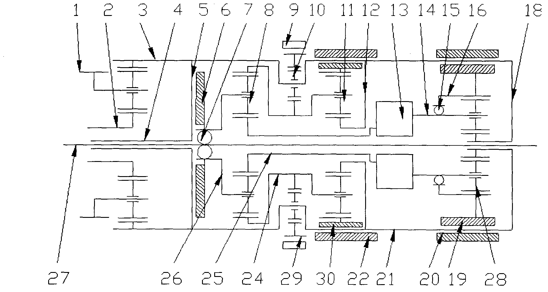
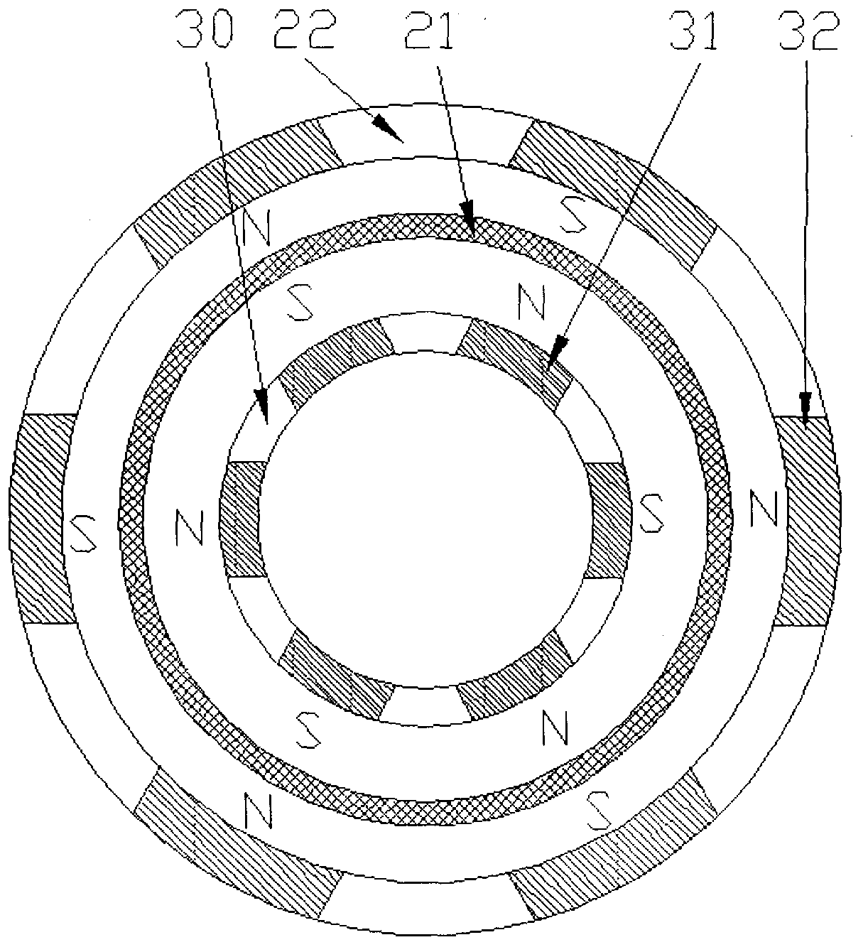
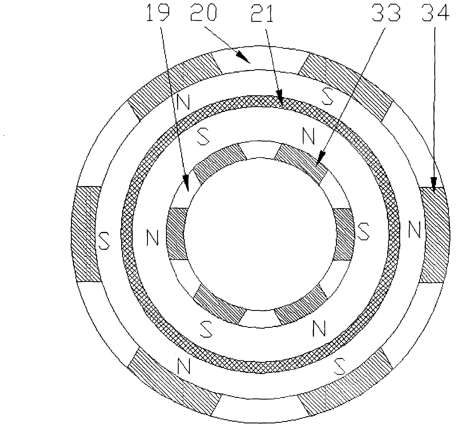
[0023] Referring to accompanying drawings 1 to 3, the structural characteristics of a control transmission mechanism of a permanent magnet and gear compound transmission continuously variable transmission are (as shown in accompanying drawings 1 to 3): the number of teeth of the internal ring gear of the distribution planetary row 8 is 109, and the sun The number of gear teeth is 81, the number of teeth of the planetary gear 27 is 14, the thin circular plate 18 is a bakelite board for electricians, and the thickness is 1mm. The gear ratios of the inner ring gear and the sun gear of the planet row 28 are both 1.5, and the arrangement positions of the permanent magnets on the moving part 30 of the permanent magnetic flexible locking mechanism and the fixed part 22 of the permanent magnetic flexible locking mechanism are shown in Figure 2. The arrangement positions of the permanent magnets on the movable part (19) of the flexible locking mechanism and the fixed part 20 of the perm...


PUM


Abstract

The invention relates to a drive control mechanism of a permanent magnetic and gear compound drive continuously variable transmission. A distribution planet row is arranged to divide the power required to be transferred into two ways, one way is that the power is fed back directly through gear drive, and the other way is that the power is fed back through a permanent magnetic slip frequency drive mechanism; a planetary gear system mechanism is designed in the two ways, and is used for transferring power between driving and driven mechanisms of the continuously variable transmission and acquiring different drive specific values according to working station exchange, so that the rotation speed difference of the driving and driven elements of the permanent magnetic slip frequency drive mechanism is less so as to acquire higher efficiency; and the torque of the continuously variable transmission varies continuously along with the drive ratio. The specific structure characteristics are that the drive control mechanism of the permanent magnetic and gear compound drive continuously variable transmission consists of the distribution planetary row 8, a low-speed planetary row 10, a speed-reduction planetary row 11, the permanent magnetic slip frequency drive mechanism 13, a coupling planetary row 28, two overrunning clutches 10 and two permanent magnetic flexible locking mechanisms, and is applied to the fields of vehicles, wind power generating systems, aircrafts, machine tools, industrial and mineral machinery, engineering machinery and the like.

Description

technical field [0001] The present invention relates to a control transmission mechanism of a permanent magnet and gear compound transmission continuously variable transmission. The transmission mechanism has the function of transferring power. One distribution planetary row shunts the power into two paths, one path directly passes through the gear transmission feedback, and the other path passes through The feedback of the permanent magnet slip transmission mechanism, the planetary gear train mechanism is designed in the two circuits to transfer power between the master and slave mechanisms of the continuously variable transmission, and different transmission ratios are obtained by switching according to the working conditions, so that the permanent magnet slip transmission The speed difference between the main and driven elements of the mechanism is small to obtain higher efficiency, and the torque of the continuously variable transmission can be changed steplessly with the t...

Claims


Application Information

Patent Timeline
Patent Type & Authority Applications(China)
IPC IPC(8): H02K51/00
Inventor 邹政耀
Owner NANJING INST OF TECH
Why Eureka
Try Eureka