Optical microphone
A microphone and optical technology, used in optical signal detection transducers, microphones, sensors, etc., can solve the problem of reducing the detection sensitivity of acoustic signals, and achieve the effect of improving detection sensitivity and high tolerance
- Summary
- Abstract
- Description
- Claims
- Application Information
AI Technical Summary
Problems solved by technology
Method used
Image
Examples
no. 1 Embodiment approach
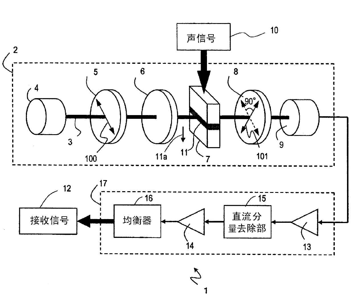
[0070] figure 1 The configuration of the first embodiment of the optical microphone of the present invention is shown. The optical microphone 1 includes a detection optical system 2 and a signal processing system 17 . The detection optical system 2 detects an acoustic signal propagating in the environment around the optical microphone 1 to generate an electrical signal, and the signal processing system 17 performs signal processing on the electrical signal to generate a reception signal 12 . Each component will be described below.
[0071]
[0072] The detection optical system 2 includes a light source 4 , a first polarizing plate 5 , an elliptical polarization generating unit 6 , a sound receiving unit 7 , a second polarizing plate 8 , and a photodetector 9 .
[0073] Light source 4 emits light 3 . In this embodiment, the light 3 used can be coherent light or incoherent light. In addition, the occupied wavelength band of the light 3 may be a single band, a narrow band,...
no. 2 Embodiment approach
[0155] Figure 16 The configuration of the first embodiment of the optical microphone of the present invention is shown. The optical microphone 1' includes a detection optical system 2' and a signal processing system 17. Similar to the first embodiment, the detection optical system 2' detects an acoustic signal propagating in the environment around the optical microphone 1' to generate an electrical signal, and the signal processing system performs signal processing on the electrical signal to generate a received signal 12. . exist Figure 16 In , the same reference numerals are assigned to the same components as those in the first embodiment. In this embodiment, a quarter-wave plate 92 is used as the elliptically polarized generation unit 6 .
[0156] In the optical microphone 1', the relative angles of the optical axes of the first polarizing plate 5, the second polarizing plate 8, and the 1 / 4 wavelength plate 92 serving as the elliptical polarization generator 6 are dif...
no. 3 Embodiment approach
[0166] Figure 19 (a) to (d) show the third embodiment of the optical microphone of the present invention. In these embodiments, although the signal processing unit is not shown, the signal processing unit described in the first and second embodiments is included. In the first and second embodiments, the detection optical systems 2, 2' have components arranged in a row along the light beam 3. However, the components in the detection optical systems 2, 2' may not be arranged in a row. In this embodiment, reflected light is used to form the optical path of the detection optical system.
[0167] Figure 19 The optical microphone shown in (a) includes a light source 4 , a first polarizer 5 , an elliptical polarization generator 6 , a second polarizer 8 , a photodetector 9 , a sound receiver 7 , a beam splitter 201 , and a mirror 202 .
[0168]The light 3 emitted from the light source passes through the first polarizer 5 and the elliptically polarized generation unit 6 and ente...
PUM
 Abstract
Description
Claims
Application Information
 - R&D
- Intellectual Property
- Life Sciences
- Materials
- Tech Scout
- Unparalleled Data Quality
- Higher Quality Content
- 60% Fewer Hallucinations
Browse by: Latest US Patents, China's latest patents, Technical Efficacy Thesaurus, Application Domain, Technology Topic, Popular Technical Reports.
© 2025 PatSnap. All rights reserved.Legal|Privacy policy|Modern Slavery Act Transparency Statement|Sitemap|About US| Contact US: help@patsnap.com


