Eureka AIR delivers breakthrough ideas for toughest innovation challenges, trusted by R&D personnel around the world.

Pulse forming network based on double-capacitor structure

A dual-capacitor and capacitor technology, applied in the field of high-voltage pulse square wave generation and pulse formation network, can solve the problems of low energy storage density, poor reliability, and high impedance, and achieve high energy storage density, compact structure, and reduced level effect of numbers

Active Publication Date: 2013-08-07
九源高能科技有限公司
View PDF5 Cites 11 Cited by
  • Summary
  • Abstract
  • Description
  • Claims
  • Application Information

AI Technical Summary

Problems solved by technology

Theoretical calculations show that the more the network stages of the LC loop, the more stable the pulse width, but in actual industrial applications, because the film capacitor pulse forming network is limited by the traditional film capacitor technology, it is bulky and heavy, while the ceramic capacitor pulse forming network is limited by ceramics. Due to the limitations of capacitor technology, short life, high impedance, low energy storage density, and poor reliability; so too many LC loops often cause the final pulse forming network to be huge in size, which cannot meet actual use
However, reducing the number of network stages of the LC loop cannot obtain ideal pulses. Therefore, it is of great significance for the miniaturization and practical development of pulse power technology to seek forming lines with small volume, high voltage transmission efficiency, and large energy storage.

Method used


Image

  • Pulse forming network based on double-capacitor structure
  • Pulse forming network based on double-capacitor structure
  • Pulse forming network based on double-capacitor structure

Examples


Embodiment Construction

[0028] The present invention will be further described below in conjunction with the accompanying drawings.

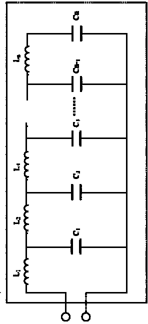
[0029] Such as figure 1 As shown, the circuit diagram is the circuit used in the prior art. The LC loop network series used in the circuit is generally in the range of 6-10. The capacitors in the network generally use ceramic capacitors and film capacitors, because these two capacitors are affected by traditional technology. Limitation, short life, high impedance, low energy storage density, poor reliability, large volume, and bulky, the general volume of the pulse forming network that is often made into a finished product is 1000mm long × 150mm wide × 150mm high, and the volume of the pulse forming network under this volume Too large, very inconvenient for transportation and practicality, and cannot meet the requirements of the miniaturization of the current process.

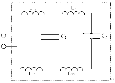
[0030] Such as figure 2 As shown, the circuit diagram is the circuit of the present invention. Th...


PUM


Abstract

The invention discloses a pulse forming network based on a double-capacitor structure and belongs to the technical field of pulse power. The pulse forming network is mainly used for generating high-voltage pulse square waves. A base circuit of the pulse forming network comprises a capacitor C1 and a capacitor C2, a self-inductor LC1 and a self-inductor LC2 of the capacitor C1 and the capacitor C2 and four wired inductors L11, L12, L21 and L22, wherein the capacitance of two capacitors is non-uniform; and a capacitance value of the capacitor C2 is greater than that of the capacitor C1. By adopting high-voltage pulse capacitors as energy storage units, the pulse forming network disclosed by the invention has the advantages of high energy-storing density; and by adopting a double-capacitor pulse forming system, the series of the pulse forming network is reduced, the defect that pulse square waves cannot be formed by a single-capacitor system is overcome and fast leading edge and quasi-pulse square wave output can be realized. The pulse forming network has the advantages of compact structure, small size, high voltage resistance, great energy-storing density and high reliability. The pulse forming system can be applied to pulse power systems with hundred-nanosecond grades.

Description

technical field [0001] The invention relates to a pulse forming network, in particular to a pulse forming network based on a double-capacitor structure, which belongs to the technical field of pulse power and is mainly used for generating high-voltage pulse square waves. Background technique [0002] In the pulse power system, the pulse forming line is one of the important components. In the 1960s, J.C. Martin of the United Kingdom proposed the concept of using the forming line to obtain nanosecond high-voltage pulses. After decades of hard work, pulse forming lines have been successfully applied to various types of pulse power devices. However, the pulse forming line, which is a key component of a high-power pulse source, currently has the problem of large volume, which needs to be solved urgently. [0003] According to the classification of capacitors, there are mainly two types of pulse forming networks used in pulse power systems: ceramic capacitor pulse forming network...

Claims


Application Information

Patent Timeline
IPC IPC(8): H03K3/02
Inventor 宋法伦金晓秦风甘延青龚海涛
Owner 九源高能科技有限公司
Why Eureka
Eureka Blog
Learn More