
Graphite dust collector

A technology of graphite dust and dust removal device, which is applied in the direction of combination device, dispersion particle separation, chemical instruments and methods, etc., can solve the problems of general dust removal effect, difficult to remove, safety threats of workshop vehicles and pedestrians, etc., to avoid pollution and human health Hazardous, good follower lubrication and cooling, good dust removal effect

Inactive Publication Date: 2013-08-14
ANHUI UNIV OF SCI & TECH
View PDF0 Cites 8 Cited by
  • Summary
  • Abstract
  • Description
  • Claims
  • Application Information

AI Technical Summary

Problems solved by technology

At the same time, due to the lubricating effect of graphite, the graphite dust in the air falls to the workshop floor and is difficult to remove. Over time, a layer of graphite lubricating film will be formed on the ground, resulting in smooth ground, which poses a huge threat to the safety of vehicles and pedestrians in the workshop.
[0003] Machining dust removal technology has been continuously improved, but so far it cannot fully meet the actual production needs
At present, the most common way for enterprises to control dust pollution is to use wet processing, but for boring machine processing, deep hole processing, or large-scale washing processing, the water spray port is fixed-point water spraying, and the dust removal effect is average.
[0004] At present, the prior art does not have a kind of dedusting equipment specially used for machine tools, therefore, a special solution to the pollution problem of escaped graphite in the processing of ductile iron is quite urgently needed

Method used


Image

  • Graphite dust collector
  • Graphite dust collector

Examples


Embodiment Construction

[0017] In order to make the innovative features, implementation means, functional principles and objectives achieved by the present invention easier to understand, the present invention will be further described below in conjunction with specific embodiments and schematic diagrams.

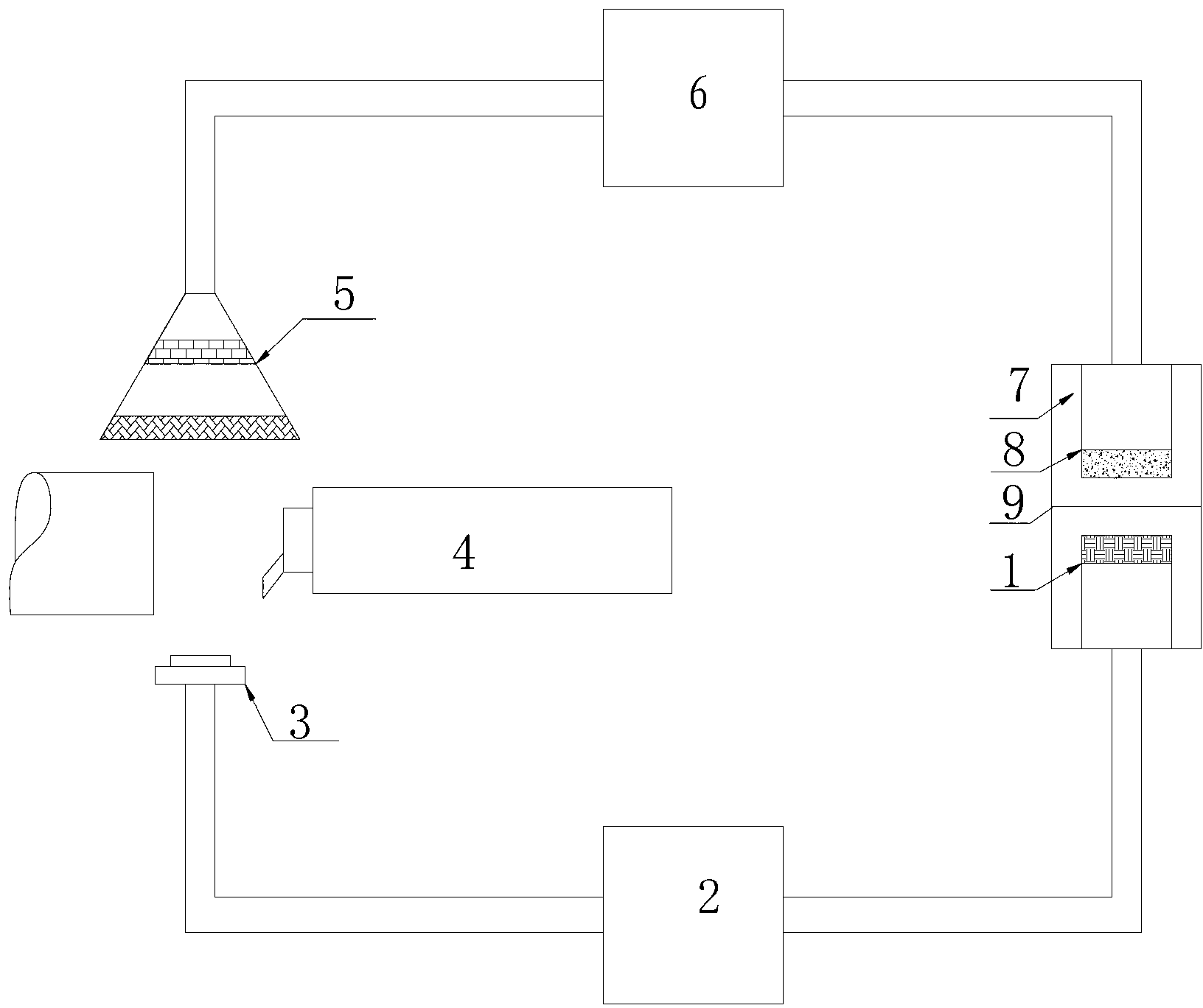
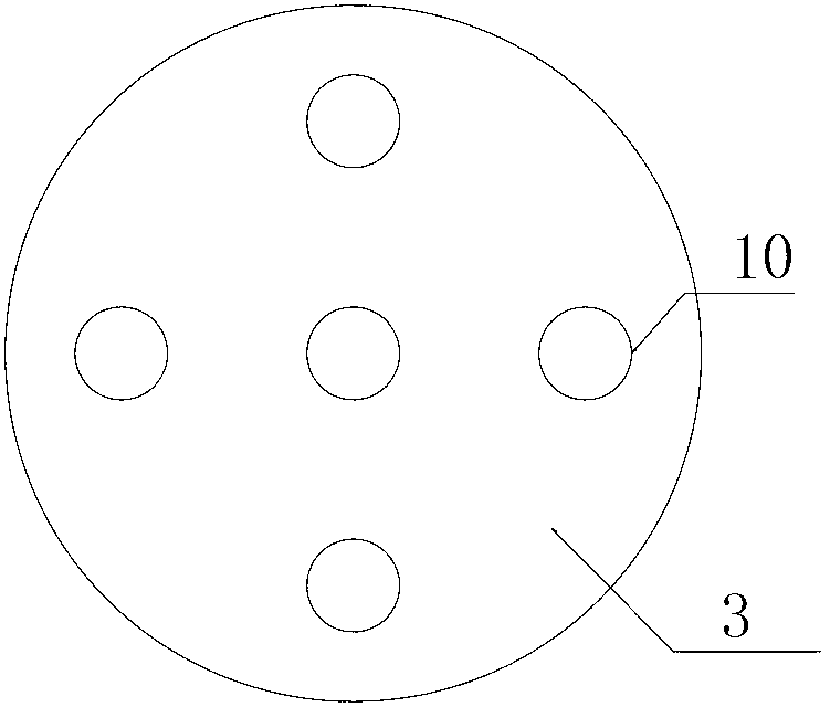
[0018] Referring to the schematic diagram, an embodiment of the present invention provides a graphite dust removal device, which includes a chip fluid filter 1 for filtering the chip fluid entering the chip fluid pump 2; the filtered chip fluid passes through the chip fluid pump to form high-pressure chips The liquid enters the self-rotating atomizing nozzle 3 to form an atomized chip liquid; the universal chip liquid pipe can adjust the position and direction of the nozzle; the atomized chip liquid captures the graphite dust that is free near the processing surface and is sucked by the vacuum cleaner 5 , and the aerosol mixture is preliminarily treated through the filter screen and the magnetized ...


PUM


Abstract

The invention provides a graphite dust collector which comprises an atomizer, a chip liquid pump, a chip liquid filtering screen, a dust absorption cover and a water-bath-type filter, wherein the atomizer is connected with the chip liquid pump; the chip liquid pump is connected with the chip liquid filtering screen through a chip liquid pipe; the chip liquid filtering screen intrudes into a chip liquid box; the dust absorption cover is internally provided with a common filtering screen and a magnetized filtering screen respectively, and is connected with the air intake end of an axial-flow-type fan; the water-bath-type filter is connected with the air exhaust end of the axial-flow-type fan, and intrudes into the chip liquid box; the atomizer atomizes and sprays out a high-pressure chip liquid, and the atomized chip liquid captures graphite dust in air; the dust absorption cover absorbs the captured atomized chip liquid and filters twice; the atomized chip liquid is filtered by the water-bath-type filter, and clean air is exhausted; and the chip liquid by the filtering screen arranged in the chip liquid box is subjected to secondary filtering, and then enters the chip liquid pump so as to form circulation. Visibly, the device captures the graphite dust generated during a ball graphite cast iron machining process through the atomized chip liquid, and achieves a dust collection effect through water bath filtration.

Description

technical field [0001] The invention relates to the auxiliary field of nodular cast iron processing in the mechanical processing industry, in particular to a dust removal device for graphite dust generated during the machining of nodular cast iron. Background technique [0002] Dust pollution is a very serious problem affecting human health. In the mechanical processing industry, especially in the production process of tractors, engines, machine tools, etc., a large number of enterprises that use ductile iron as part blanks, ductile iron contains a large amount of spherical graphite, due to cutting force shear damage during processing, chips are peeled off At the same time, the spherical graphite also falls off. Due to the low density of graphite, the rotating machine tool forms a small air vortex, and the spherical graphite floats in the air, forming dust pollution mainly composed of graphite, which seriously affects the health of operators. At the same time, due to the lu...

Claims


Application Information

Patent Timeline
Patent Type & Authority Applications(China)
IPC IPC(8): B01D50/00
Inventor 秦秀秀张安宁闫朝辉尹中会张大伟徐春云金立
Owner ANHUI UNIV OF SCI & TECH
Learn More