Polycrystalline silicon ingot furnace and method for preparing polycrystalline silicon ingot with even and fine crystalline grains

A polysilicon ingot casting furnace and polysilicon technology, applied in the field of solar cells, can solve the problems affecting the verticality, impact, and defects of polysilicon ingots, etc.

Inactive Publication Date: 2013-08-14
TIANJIN YINGLI NEW ENERGY RESOURCES
View PDF7 Cites 10 Cited by
  • Summary
  • Abstract
  • Description
  • Claims
  • Application Information

AI Technical Summary

Problems solved by technology

[0006] The method of increasing the heat dissipation rate at the bottom of the ingot furnace at the initial stage of crystal growth to increase the degree of supercooling can achieve the purpose of growing small grains, but this production method has the following disadvantages: 1. The sudden increase in the temperature change rate has a negative impact on the crucible and coating If there is a defect in the crucible coating, production accidents such as sticking crucible or even leakage are likely to occur; 2. The sudden increase in cooling rate will affect the subsequent normal cry

Method used


Image

  • Polycrystalline silicon ingot furnace and method for preparing polycrystalline silicon ingot with even and fine crystalline grains
  • Polycrystalline silicon ingot furnace and method for preparing polycrystalline silicon ingot with even and fine crystalline grains
  • Polycrystalline silicon ingot furnace and method for preparing polycrystalline silicon ingot with even and fine crystalline grains

Examples


Embodiment 1

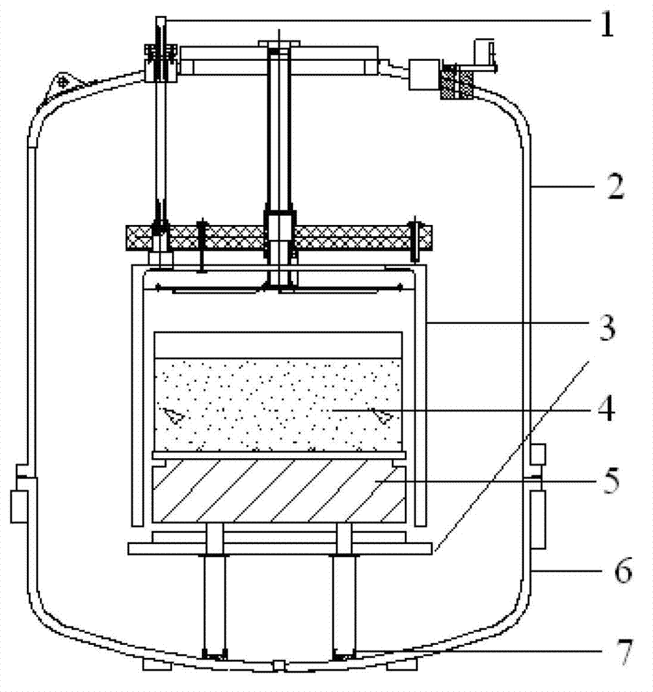
[0040] like figure 2 as shown, figure 2 It is a schematic structural diagram of a polysilicon ingot casting furnace, which includes: a heat insulation cage lifting mechanism 1, an upper furnace body 2, a heat insulation cage 3, a crucible assembly 4, a directional coagulation aid block 5, a lower furnace body 6, a support A column 7, an ultrasonic generator 8, the ultrasonic generator 8 is arranged at the bottom of the outer wall of the lower furnace body 6.

Embodiment 2

[0042] Load the polysilicon material to the inner wall coated with Si 3 N 4 In the quartz crucible, place the crucible on the hollow graphite block, that is, the directional coagulation aid block (DS block); then, close the lower furnace chamber for vacuuming operation, and heat up after the system completes the leak detection operation; the surrounding and top of the crucible A heater is installed, and the silicon material is heated after the power is turned on. The heating process lasts for 15 hours until the silicon material is completely melted, and then the heat insulation cage is used to raise the position of the heat insulation cage to accelerate the heat from the directional coagulation. The speed of outward diffusion will cool it, thereby indirectly taking away the heat in the crucible, and finally form a bottom-up vertical temperature gradient in the silicon solution; under the action of this temperature gradient, the silicon material will start to solidify from the ...


PUM


Abstract

The invention provides a polycrystalline silicon ingot furnace and a method for preparing a polycrystalline silicon ingot with even and fine crystalline grains. The polycrystalline silicon ingot furnace comprises a heat insulating cage lifting mechanism, an upper furnace body, a heat insulating cage, a crucible assembly, a directional coagulantion enhancement block, a lower furnace body, a support pillar and an ultrasonic generator, wherein the ultrasonic generator is arranged at the bottom of the outer wall of the lower furnace body, or on the side surface of the outer wall of the upper furnace body. The polycrystalline silicon ingot furnace and the method are characterized in that in the process of producing the polycrystalline silicon ingot, the ultrasonic generator is opened when the polycrystalline melt is in critical nucleation state, and the ultrasonic generator is closed in 1-20 min, and mechanical oscillation is introduced in initial stage of polycrystalline nucleation, so that the polycrystalline silicon ingot with even and fine in crystalline grains can be formed.

Description

technical field [0001] The invention relates to the technical field of solar cells, in particular to a polysilicon ingot furnace and a method for preparing polysilicon ingots with uniform and fine crystal grains. Background technique [0002] Solar cells are one of the fastest growing industries in recent years, with a high growth rate of more than 50%. Among various types of solar cells, crystalline silicon solar cells maintain a leading position due to their high conversion rate and mature technology. The complete industrial chain of crystalline silicon solar photovoltaic modules includes four parts: casting ingots, slices, cells and modules, while casting polycrystalline silicon ingots is the first step in the production of polycrystalline silicon solar photovoltaic modules. [0003] At present, polysilicon ingot casting furnaces are generally used for casting polysilicon ingots. figure 1 It is a schematic diagram of the structure of a polysilicon ingot casting furnace,...

Claims


Application Information

Patent Timeline
IPC IPC(8): C30B30/00C30B28/06C30B29/06
Inventor 王悦刘华戴允蛟任建华唐自成
Owner TIANJIN YINGLI NEW ENERGY RESOURCES
Why Eureka
Try Eureka