
Method for exploiting heavy oil reservoir by strengthening in-situ oil combustion

A technology for heavy oil reservoirs and burning oil layers, which is applied in the fields of fluid extraction, earthwork drilling, wellbore/well components, etc., can solve the problems of reduced heat release of crude oil, failure of field tests, and failure of peripheral crude oil to ignite, etc., to achieve safety Combustion oil layer development, realizing the effect of combustion oil layer development

Active Publication Date: 2013-08-14
PETROCHINA CO LTD
View PDF6 Cites 11 Cited by
  • Summary
  • Abstract
  • Description
  • Claims
  • Application Information

AI Technical Summary

Problems solved by technology

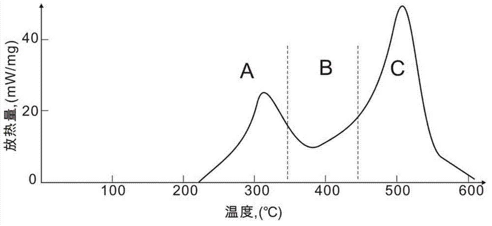
However, in the combustion oil layer recovery technology, according to the heat release test results of the oxidation reaction of crude oil in different temperature ranges, it is shown that the combustion of crude oil needs to start from the low temperature (oxidation) zone (see figure 1 Region A in the region, where heavy oil undergoes low-temperature oxidation reaction) jumps to the high-temperature (combustion) region (see figure 1 The area C in the middle, in which the high-temperature combustion reaction of heavy oil occurs) can achieve successful high-temperature combustion, and the temperature range between the low-temperature area and the high-temperature area (see figure 1 The area B in the middle, hereinafter referred to as: low-heat area), is affected by the oxidation reaction components in this area, and the heat release of crude oil is significantly reduced. If it reaches the ignition point, the surrounding crude oil will not be able to ignite. At the same time, if the oxygen concentration in this area does not reach the minimum oxygen concentration required for combustion, the combustion will be extinguished, the continuous combustion process will stop, and the mine test will fail.

Method used


Image

  • Method for exploiting heavy oil reservoir by strengthening in-situ oil combustion

Examples


Embodiment 1

[0026] This embodiment provides a method for intensifying the exploitation of heavy oil reservoirs by burning oil layers. The underground crude oil viscosity of the heavy oil reservoirs is 10,000 centipoise; the following steps are adopted:

[0027] (1) Five-point vertical well injection-production well pattern is set up in the production area of ​​heavy oil reservoir, and the well spacing between adjacent injection wells and production wells is 150-300m; (2) The oil layer is ignited by chemical ignition; ( 3) Continuously inject air from the vertical well injection well into the reservoir to maintain combustion, and the air injection speed is 10000Nm 3 / day; (4) The production well is opened, and continuous oil production is adopted by the self-spraying method, and the maximum liquid drainage speed of the production well is 50Nm 3 / day, the maximum exhaust velocity is 10000Nm 3 / day; (5) Air injection volume of injection well every 100000Nm 3 , instead inject 1m of hydrogen...

Embodiment 2

[0030] This embodiment provides a method for intensifying the exploitation of heavy oil reservoirs by burning oil layers. The underground crude oil viscosity of the heavy oil reservoirs is 500,000 centipoise; the following steps are adopted:

[0031] (1) In the production area of ​​heavy oil reservoirs, an inverted seven-point vertical well injection-production well pattern is set up, and the well spacing between adjacent injection wells and production wells is 220m; (2) The oil layer is ignited by electric ignition; (3 ) Continuously inject air from the vertical well injection well into the reservoir to maintain combustion, and the injected air speed is 12000Nm 3 / day; (4) The production well is opened, and the electric submersible pump with high temperature resistance above 350℃ is used for continuous oil production, and the maximum liquid drainage speed of the production well is 80Nm 3 / day, the maximum exhaust velocity is 12000Nm 3 / day; (5) Air injection volume of inject...

Embodiment 3

[0034] This embodiment provides a method for intensifying the exploitation of heavy oil reservoirs by burning oil layers. The underground crude oil viscosity of the heavy oil reservoirs is 1,000,000 centipoise; the following steps are used:

[0035](1) In the production area of ​​heavy oil reservoirs, an inverted nine-point vertical well injection-production well pattern is set up, and the well spacing between adjacent injection wells and production wells is 300m; (2) The oil layer is ignited by electric ignition; (3 ) Continuously inject air from the vertical well injection well into the oil reservoir to maintain combustion, and the air injection speed is 15000Nm 3 / day; (4) The production well is opened, and the artificial lift method of the screw pump with a high temperature resistance above 350°C is used for continuous oil production, and the maximum liquid drainage speed of the production well is 100Nm 3 / day, the maximum exhaust velocity is 15000Nm 3 / day; (5) Air injec...


PUM

PropertyMeasurementUnit
Viscosityaaaaaaaaaa
Viscosityaaaaaaaaaa

Abstract

The invention provides a method for exploiting a heavy oil reservoir by strengthening in-situ oil combustion. The method includes: arranging a vertical injection-production well pattern including an injection well and a production well in an exploiting area of the heavy oil reservoir; lighting oil layers by means of chemical ignition or electric ignition; continuously injecting air from the vertical injection well to maintain combustion; continuously exploiting through the production well; injecting 1-3m<3> of hydrogen peroxide slug 30-50% in mass concentration when every 100000-150000Nm<3> of air is injected in the injection well, and alternately injecting in this way; and closely monitoring oxygen content and temperature of gas produced by the production well, and timely adjusting slug injection parameters. Hydrogen peroxide rapidly decomposes at high temperature in the oil layers, so that a large amount of heat and oxygen is provided for oil layer combustion, strengthened combustion is achieved, heavy oil combustion rapidly and favorably crosses a low-heat area to enter a high-temperature combustion area, and continuous oil combustion exploiting is achieved.

Description

technical field [0001] The invention relates to a method for injecting hydrogen peroxide to intensify the exploitation of heavy oil reservoirs by burning oil layers, and is mainly used for the development of heavy oil reservoirs to increase the recovery rate of crude oil. Background technique [0002] The main development technologies of heavy oil reservoirs are steam injection development technology (steam huff and puff, steam flooding, steam assisted gravity drainage) and air injection high temperature combustion development technology (combustion reservoir recovery technology). Steam injection development technology, due to the large heat loss along the steam injection process from the outlet of the surface boiler to the bottom well reservoir, the dryness of the steam entering the heavy oil reservoir, especially the medium and deep heavy oil reservoir is low, and the steam spreads The volume is often small, resulting in high energy consumption for steam injection developm...

Claims


Application Information

Patent Timeline
IPC IPC(8): E21B43/243
Inventor 吴永彬蒋有伟赵欣张霞林
Owner PETROCHINA CO LTD
Learn More