
Common-optical path polarization point diffraction phase-shift interference wavefront sensor

A wavefront sensor, point diffraction phase-shifting technology, applied in optical radiation measurement, instruments, optics, etc., can solve the problem of strong resistance to environmental vibration and atmospheric interference, test light waves and reference light waves do not share the same path, and difficulty in PDI mask processing Advanced problems, to achieve the effect of large measurement dynamic range, strong anti-atmospheric interference and environmental vibration capabilities, and simple wavefront reconstruction algorithm

Inactive Publication Date: 2013-08-14
INNER MONGOLIA UNIV OF TECH
View PDF5 Cites 11 Cited by
  • Summary
  • Abstract
  • Description
  • Claims
  • Application Information

AI Technical Summary

Problems solved by technology

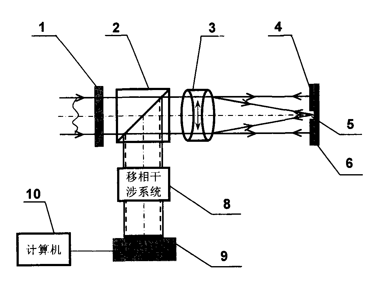
[0008] The problem solved by the technology of the present invention is: in order to solve the shortcomings of the existing point diffraction interference wavefront sensing technology, such as the test light wave and the reference light wave are not in the same path, the PDI mask is difficult to process, the phase shift is difficult, and the fringe contrast cannot be adjusted. , the present invention provides a common optical path polarization point diffraction phase-shifting interference wavefront sensor, which uses a birefringent lens and a polarized PDI mask to generate a common optical path orthogonal linearly polarized reference light and test light, and uses phase-shifting interference technology to reconstruct the wavefront to be measured Phase, so as to achieve the purpose of strong resistance to environmental vibration and atmospheric interference, high contrast of interference fringes, self-referencing interference, and high measurement accuracy

Method used


Image

  • Common-optical path polarization point diffraction phase-shift interference wavefront sensor
  • Common-optical path polarization point diffraction phase-shift interference wavefront sensor
  • Common-optical path polarization point diffraction phase-shift interference wavefront sensor

Examples


Embodiment Construction

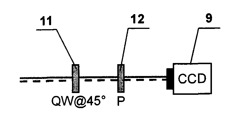
[0024] The common optical path polarization point diffraction phase-shifting interference wavefront sensor of the present invention, such as figure 1 As shown, it includes a polarizer 1, a first birefringent lens 3 and a second birefringent lens 7, a phase-shifting interference system 8, a CCD sensor 9, and a computer 10; A polarized PDI mask 4 containing a pinhole 5 is added, the vibration direction of which is perpendicular to the vibration direction of the converged light beam passing through the first birefringent lens 3 . The first birefringent lens 3 and the second birefringent lens 7 are a symmetrical birefringent triplet lens, composed of a calcite biconcave lens located in the middle and two glass biconvex lenses, and the optical axis of the calcite is located at the lens plane Inside, the focal points of the two lenses coincide and the directions of the fast axes are parallel; the birefringent lenses 3 and 7 can divide a beam of linearly polarized parallel beams into...


PUM


Abstract

The invention relates to a common-optical path polarization point diffraction phase-shift interference wavefront sensor, which comprises a polaroid, a first double refraction lens, a second double refraction lens, a phase-shift interference system, a CCD (Charge Coupled Device) sensor and a computer, as well as a polarization PDI (Point-diffraction Interferometer) mask plate provided with a needle hole and additionally arranged at a confocal plane of the first and second double refraction lenses, wherein a linearly polarized light beam to be detected is divided into two beams by the first double refraction lens, E light is converged at the needle hole of the polarization PDI mask plate to be subjected to small hole diffraction so as to serve as reference light, and O light passes through the polarization PDI mask plate nearly without decrement to serve as testing light; the reference light and the testing light pass through the phase shift interference system to form a four-frame time or space phase shift interference figure; streak contrast gradient is adjusted through rotating the polaroid; and then a phase shift algorithm is adopted to re-establish a phase position of a wavefront to be detected. According to the invention, the wavefront sensor adopts a common-optical path, dispenses with special reference light, is strong in system stability and adjustable in streak contrast gradient, and is suitable for high-precision detection for dynamic and static stage of various wavefront phase positions.

Description

technical field [0001] The invention relates to a key device in the fields of adaptive optics, wavefront detection, optical element detection and the like, in particular to a common optical path polarization point diffraction phase-shifting interference wavefront sensor. Background technique [0002] The wavefront sensor is an important key device in the adaptive system, which is used to detect the wavefront phase of the incident beam. According to the relationship between the measured signal and the wavefront, wavefront sensors can be divided into three categories: the first category is to restore the wavefront phase by measuring the wavefront slope, such as Hartmann wavefront sensors, transverse shear interference wavefront sensors (Appl .Opt.2001, 41(19): 3781-3789; Intense Laser and Particle Beam, 2000, 12(3): 269-272); the second type is to restore the wavefront phase by measuring the wavefront curvature, such as curvature wavefront sensor (J.Opt.Soc.Am.A, 1994, 11(5):...

Claims


Application Information

Patent Timeline
Patent Type & Authority Applications(China)
IPC IPC(8): G01J9/02G02B27/10
Inventor 白福忠王晓强刘珍索晓红吴亚琴田枫
Owner INNER MONGOLIA UNIV OF TECH
Learn More