Non-intrusive pipeline real-time monitoring, prewarning and fault locating system

A real-time monitoring and fault location technology, applied in pipeline systems, fluid pressure measurement using acoustic methods, gas/liquid distribution and storage, etc. Accuracy, impact reduction, damage avoidance effect

Inactive Publication Date: 2013-08-14
SOUTHWEST PETROLEUM UNIV
View PDF5 Cites 39 Cited by
  • Summary
  • Abstract
  • Description
  • Claims
  • Application Information

AI Technical Summary

Problems solved by technology

People have done a lot of exploration and research on improving this tool, and many new products have been produced, but a general survey of the market finds that non-invasive pipeline real-time monitoring and early warning and fault location devices have not yet been well developed
[0003] Chinese patent application No. 921087772 "Ultrasonic pressure measurement method and instrument outside the pipe" discloses a pressure measurement method and instrument based on ultrasonic waves. The instrument can only achieve one measurement and cannot monitor the pipeline pressure in real time. The main problems are as follows: firstly, the echo must be judged, which increases the complexity of the circuit; secondly, if the reflective surface of the inner wall of the pipeline is not smooth, it will have a great impact on the echo, so that the measurement can be obtained The results will produce errors; finally, the temperature will have a great influence on the transmission of ultrasonic waves, and the instrument has not made corresponding corrections for the temperature influence
Similarly, this method does not propose real-time monitoring of pipeline pressure, and at the same time, this method does not compensate for the influence of temperature on pipeline pressure, nor does it compensate for the hysteresis time of components, so that the measured pressure results will have a large difference. errors, and the literature does not mention the real-time monitoring of pipeline temperature and pressure

Method used


Image

  • Non-intrusive pipeline real-time monitoring, prewarning and fault locating system
  • Non-intrusive pipeline real-time monitoring, prewarning and fault locating system
  • Non-intrusive pipeline real-time monitoring, prewarning and fault locating system

Examples


Embodiment Construction

[0019] The present invention will be further described below in conjunction with the accompanying drawings.

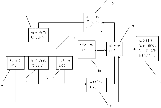
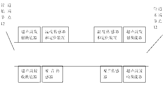
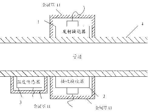
[0020] Such as figure 1As shown, the present invention is a non-invasive pipeline real-time monitoring and early warning and fault location system, which mainly consists of a transmitting transducer 1, a receiving transducer 2, a temperature sensor 3, a pipeline 4, an ultrasonic transmitting control unit 5, a receiving transducer Control unit 6, data processing unit 7, keyboard scanning, display, alarm, computer communication unit 8, and noise sensor 9. Transmitting transducer 1 and receiving transducer 2 are a pair of dual-crystal straight probes, and the center frequency of transmitting transducer 1 is 2.5MHZ. The data processing unit 7 adopts TMS320F2812, the DSP is low in cost, the clock frequency can reach 150MHz, the operation and data processing speed is fast, and the internal resources are abundant. The main function of the ultrasonic transmitting control uni...


PUM


Abstract

The invention discloses a non-intrusive pipeline real-time monitoring, prewarning and fault locating system, and belongs to the technical field of pipeline system temperature and pressure monitoring, and pipeline system fault diagnosis. The method adopted by the invention comprises the following three aspects: temperature and pressure real-time monitoring, prewarning, and fault locating; the pressure monitoring and the temperature monitoring adopt non-intrusive measuring methods, the pressure is monitored by adopting an ultrasonic non-invasive measuring method, the temperature is monitored by adopting a traditional temperature sensor non-invasive measuring method, and sensors for pressure monitoring and temperature monitoring are mounted on the outer wall of a pipeline; a design database is used for prewarning a fault signal; and a negative-pressure wave leak detection method is adopted for locating a fault in a pipeline system.

Description

technical field [0001] The invention relates to the technical field of monitoring the temperature and pressure of the pipeline system and the fault diagnosis of the pipeline system, in particular to a method of using ultrasonic technology to realize the real-time monitoring of the pressure outside the pipe and the fault diagnosis of the pipeline system, and to realize the real-time monitoring of the temperature outside the pipe by using a temperature sensor . Background technique [0002] The traditional pressure measurement method is to install temperature sensors and pressure sensors at the measured point, and the temperature and pressure sensing elements are directly in contact with the measured medium, and the temperature and pressure values ​​are converted into electrical signals and sent to the site in a way that is suitable for the site. External temperature transmission, including wired and wireless methods. The advantage of this method is that it is simple and dire...

Claims


Application Information

Patent Timeline
Patent Type & Authority Applications(China)
IPC IPC(8): F17D5/06G01L11/06
Inventor 罗仁泽赵发定郑勉仝迪李芮张平曹鹏付元华牛娜杨娇
Owner SOUTHWEST PETROLEUM UNIV
Why Eureka
Try Eureka