Large-scale power rectifier cabinet silicon controlled rectifier continuity detection device

A technology of continuity detection and rectifier cabinet, applied in the direction of measuring device, measuring electricity, measuring electrical variables, etc., can solve hidden dangers, insufficient detection of power components, and high commutation voltage, so as to eliminate hidden dangers and shorten the time of working with diseases. Maintenance time, the effect of a wide range of applications

Inactive Publication Date: 2013-08-14
WUHAN HONGSHAN ELECTRICAL SCI & TECH
View PDF4 Cites 7 Cited by
  • Summary
  • Abstract
  • Description
  • Claims
  • Application Information

AI Technical Summary

Problems solved by technology

Due to the harsh actual working condition of the thyristor, large current, large heat generation, and high commutation voltage, there are many difficulties in real-time detection of its operating status. At present, the conventional design of power rectifier cabinets adopts the installation of fast fuses and output Single-cabinet ammeter signal to the user in order to judge the working condition of the silicon controlled rectifier
The fast fuse is installed in series in each thyristor branch. When the thyristor short-circuits, the fast fuse exits the branch and sends a corresponding alarm signal to the user. This design can respond to a certain extent. The extreme working condition of the thyristor short circuit, but for the thyristor open circuit or the non-triggering or false triggering caused by the fault of the control circuit, it cannot be correctly judged
As for the ammeters sent to users, the criteria are rough. Even if the fault of the rectifier cabinet can be judged according to the large deviation of the current, the fault branch cannot be accurately located; In most cases, multiple thyristor rectifier cabinets need to run in parallel. If a branch fails, the current deviation will not be very large, which may cause users to relax their vigilance and cause hidden dangers.
As the capacity of the unit increases, the requirements for the excitation system and the rectifier cabinet of the excitation system are becoming increasingly strict. Insufficient detection of power components in rectifier cabinet design

Method used


Image

  • Large-scale power rectifier cabinet silicon controlled rectifier continuity detection device
  • Large-scale power rectifier cabinet silicon controlled rectifier continuity detection device
  • Large-scale power rectifier cabinet silicon controlled rectifier continuity detection device

Examples


Embodiment Construction

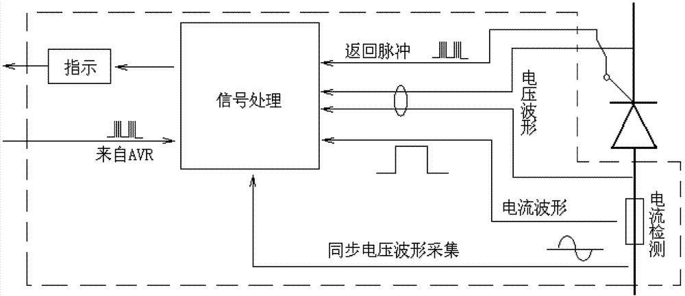
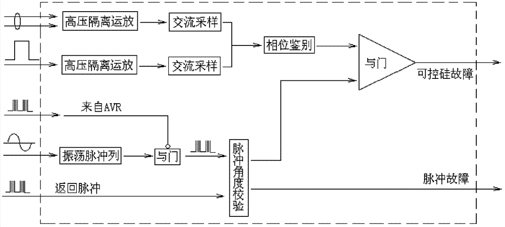
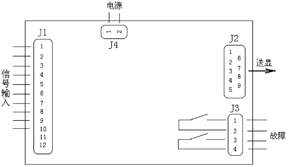
[0015] The thyristor conduction detection device is divided into three parts: signal acquisition, signal processing, and display. Signal acquisition includes thyristor bridge arm current acquisition, thyristor tube voltage drop waveform acquisition, thyristor actual trigger pulse acquisition, AVR actual trigger angle acquisition, anode synchronous voltage acquisition; the signal processing part will collect various signals Comprehensive processing to identify the fault type of the thyristor and accurately locate it; the sending display part displays the phase difference of the faulty thyristor online, and outputs the contact signal to the monitoring system. See the attached schematic diagram of the electrical principle figure 1 , the schematic diagram of the signal processing principle is attached figure 2 , the application wiring diagram see image 3 .

[0016] See figure 1 : The electrical quantity when the thyristor is working mainly includes branch current, tube volta...


PUM


Abstract

A high-power silicon controlled rectifier cabinet continuity detection device comprises three parts, namely a signal acquisition part, a signal processing part and a transmitting and displaying part, wherein the signal acquisition part acquires the bridge arm current of a silicon controlled rectifier via a sensor and measures the tube voltage drop of the silicon controlled rectifier via a low time-lag transmitter. As the bridge arm current and the tube voltage drop of the silicon controlled rectifier are opposite in phase, when the silicon controlled rectifier is cut off, the tube voltage drop is the anode alternating current line voltage; when the silicon controlled rectifier is triggered to be on, the tube voltage drop is very low as 2V approximately; each round comprises a continuity period and a cutoff period; and according to the relationship, the signal processing part can preliminarily judge whether the silicon controlled rectifier is in a controllable state.

Description

technical field [0001] The invention relates to a power rectifier cabinet for the excitation system of a medium-to-large or giant generating set, in particular to an occasion where the excitation current is large and multiple rectifier cabinets need to be connected in parallel. Background technique [0002] In the generator excitation system, the power rectifier converts AC power into DC power and provides excitation current for the generator excitation winding. It is the output part of the excitation system and the foundation of excitation. The core of its work, the reliability of its work is beyond doubt. Due to the harsh actual working condition of the thyristor, large current, large heat generation, and high commutation voltage, there are many difficulties in real-time detection of its operating status. At present, the conventional design of power rectifier cabinets adopts the installation of fast fuses and output The single-cabinet ammeter signal is given to the user i...

Claims


Application Information

Patent Timeline
Patent Type & Authority Applications(China)
IPC IPC(8): G01R31/02
Inventor 苏军余超章科峰
Owner WUHAN HONGSHAN ELECTRICAL SCI & TECH
Why Eureka
Try Eureka