Ferrite for anechoic chamber and preparation method and applications thereof

An anechoic chamber and ferrite technology, which is applied in the direction of measuring electricity, measuring electrical variables, measuring devices, etc., can solve the problems of high cost and achieve the effect of high precision and low energy consumption

Inactive Publication Date: 2013-08-21
JIANG SU YOUNG KING ELECTRONICS
View PDF4 Cites 13 Cited by
  • Summary
  • Abstract
  • Description
  • Claims
  • Application Information

AI Technical Summary

Problems solved by technology

The ferrite absorbing materials commonly used in the domestic market are generally produced by South Korea: SAMWHA CAPACITOR GROUP and Japan: TDK Corporation, but SAMWHA and TDK are expensive

Method used


Image

  • Ferrite for anechoic chamber and preparation method and applications thereof
  • Ferrite for anechoic chamber and preparation method and applications thereof
  • Ferrite for anechoic chamber and preparation method and applications thereof

Examples


Embodiment 1

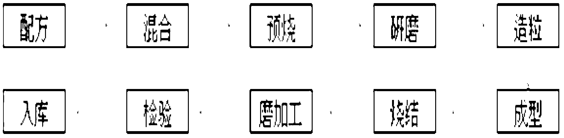
[0041] A ferrite preparation method for an anechoic chamber, the steps of which are:

[0042] (1) Configure the component Fe of each mass percentage 2 O 3 :64.6%, MnO:19.6%, ZnO:13.6%, CuO:1.5%, CoO:0.6%, SiO 2 :0.06%, CaO:0.02%, Cr 2 O 3:0.01%, Cl:0.01%;

[0043] (2) Mix the above components for powder making. The powder making adopts wet sand milling process, so that the raw materials are mixed more uniformly and then pre-fired. (3) After wet mixing, pre-fire at a temperature of 750 ° C. Burning, the atmosphere is atmospheric, and the pre-burning is kept for 5 hours; (4) After pre-burning, use a second ball mill to make a fine powder, the particle size is 1-3um, and the grinding and crushing time is 4 hours; (5) Combined with spray granulation Granulation, the particle range is 20 mesh / cm~65 mesh / cm, and the bulk density is 1.2g / cm 3 ~1.25g / cm 3 , the sliding angle is 35°; (6) A blank with a width of 100mm, a length of 100mm and a thickness of 5.2mm is formed by a mol...

Embodiment 2

[0057] Its composition and manufacturing process of the product of embodiment 2 are the same as embodiment 1, except that the grinding and pulverizing time is 12 hours.

[0058] 1. Use a laser particle size analyzer (MS2000) to analyze the particle size distribution of the powder. Its 50% particle size distribution of embodiment 2 product is 0.821 (micron), and 90% particle size distribution is 1.226 (micron), and the average grain diameter after firing is 16.1 (micron).

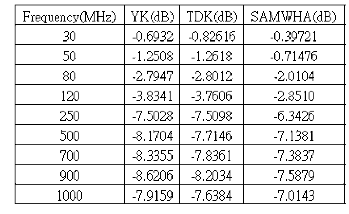
[0059] 2. Use a network analyzer to analyze the reflectivity characteristics of the product in Example 2 at 30 MHz to 1000 MHz. The following table:

[0060]

Embodiment 3

[0062] The composition and production process of the product of Example 3 are the same as those of Example 1, except that the pre-calcination temperature is 850° C., and the grinding and pulverization time is 2 hours.

[0063] 1. Use a laser particle size analyzer (MS2000) to analyze the particle size distribution of the powder. Its 50% particle size distribution of embodiment 3 product is 1.687 (micron), and 90% particle size distribution is 2.984 (micron), and the average grain diameter after firing is 13.9 (micron).

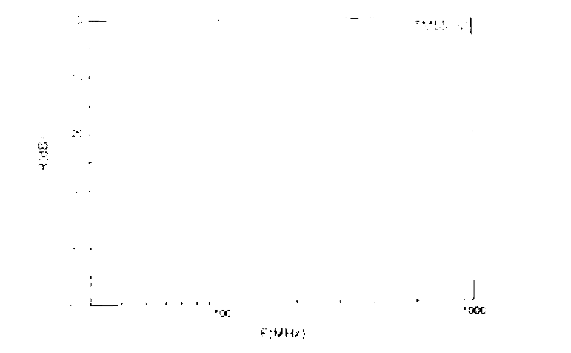
[0064] 2. Use a network analyzer to analyze the reflectivity characteristics of the product in Example 3 at 30 MHz to 1000 MHz. The following table:

[0065]


PUM

PropertyMeasurementUnit
thicknessaaaaaaaaaa
densityaaaaaaaaaa
angleaaaaaaaaaa

Abstract

The invention discloses ferrite for an anechoic chamber and a preparation method and applications thereof, and belongs to the field of ferrites. The ferrite is composed of the following components in percentage by mass: 64.6% of Fe2O3, 19.6% of MnO, 13.6% of ZnO, 1.5% of CuO, 0.6% of CoO, 0.06% of SiO2, 0.02% of CaO, 0.01% of Cr2O3 and 0.01% of Cl; and the average grain diameter of the ferrite is 13-22.3 mu m. According to the invention, under the precondition of satisfying the test requirements of the anechoic chamber on the ferrite, compared with wave-absorbing materials of ferrites for anechoic chambers commonly used in the domestic market, the production cost of the ferrite is reduced by 7-10%, the weight is lighter, and the thickness is smaller; and the installation of the ferrite is more convenient.

Description

technical field [0001] The invention relates to a manganese-zinc system ferrite soft magnetism and a manufacturing method thereof, in particular to a ferrite used in an anechoic chamber, a preparation method and an application thereof. Background technique [0002] As China becomes a major electronics manufacturing country, the demand for EMC chambers in the Chinese market is also increasing. China's demand for electromagnetic compatible anechoic chambers has increased by 5 times compared with 10 years ago. Electromagnetic compatible anechoic chambers are also called semi-radio anechoic chambers, or EMC anechoic chambers for short. Electromagnetic wave absorbing material, the ground is an ideal reflective surface. This simulates the test conditions in the open field. [0003] Each test item of electromagnetic compatibility requires a specific test site, among which the radiated emission and radiated immunity tests have the most stringent requirements on the site. Since th...

Claims


Application Information

Patent Timeline
Patent Type & Authority Applications(China)
IPC IPC(8): C04B35/26C04B35/622G01R31/00
Inventor 郑正吉游建章方瑜渊
Owner JIANG SU YOUNG KING ELECTRONICS
Why Eureka
Try Eureka