Eureka AIR delivers breakthrough ideas for toughest innovation challenges, trusted by R&D personnel around the world.

Insulated gate bipolar transistor (IGBT) device with positive temperature coefficient emitter ballast resistance

A technology of positive temperature coefficient and ballast resistance, which is applied in the manufacture of electrical components, semiconductor devices, semiconductor/solid-state devices, etc. The problem of high doping concentration can improve the short-circuit capability, increase the EBR resistance, and reduce the forward voltage drop.

Inactive Publication Date: 2013-08-21
UNIV OF ELECTRONICS SCI & TECH OF CHINA +1
View PDF5 Cites 8 Cited by
  • Summary
  • Abstract
  • Description
  • Claims
  • Application Information

AI Technical Summary

Problems solved by technology

However, in the traditional EBR-IGBT structure, the emitter ballast resistor is formed by a strip N + The emitter region is formed because N + The doping concentration in the emission region is high, the mobility is mainly dominated by ionized impurity scattering, and the resistance value usually exhibits a negative temperature coefficient
Under the condition of small current and low temperature, the EBR resistance value is large, which will increase the conduction loss of the IGBT power device. However, under the condition of high temperature and high current, the EBR resistance value becomes smaller, and the effect of suppressing the latch-up of the IGBT device cannot be achieved.

Method used


Image

  • Insulated gate bipolar transistor (IGBT) device with positive temperature coefficient emitter ballast resistance
  • Insulated gate bipolar transistor (IGBT) device with positive temperature coefficient emitter ballast resistance
  • Insulated gate bipolar transistor (IGBT) device with positive temperature coefficient emitter ballast resistance

Examples


Embodiment Construction

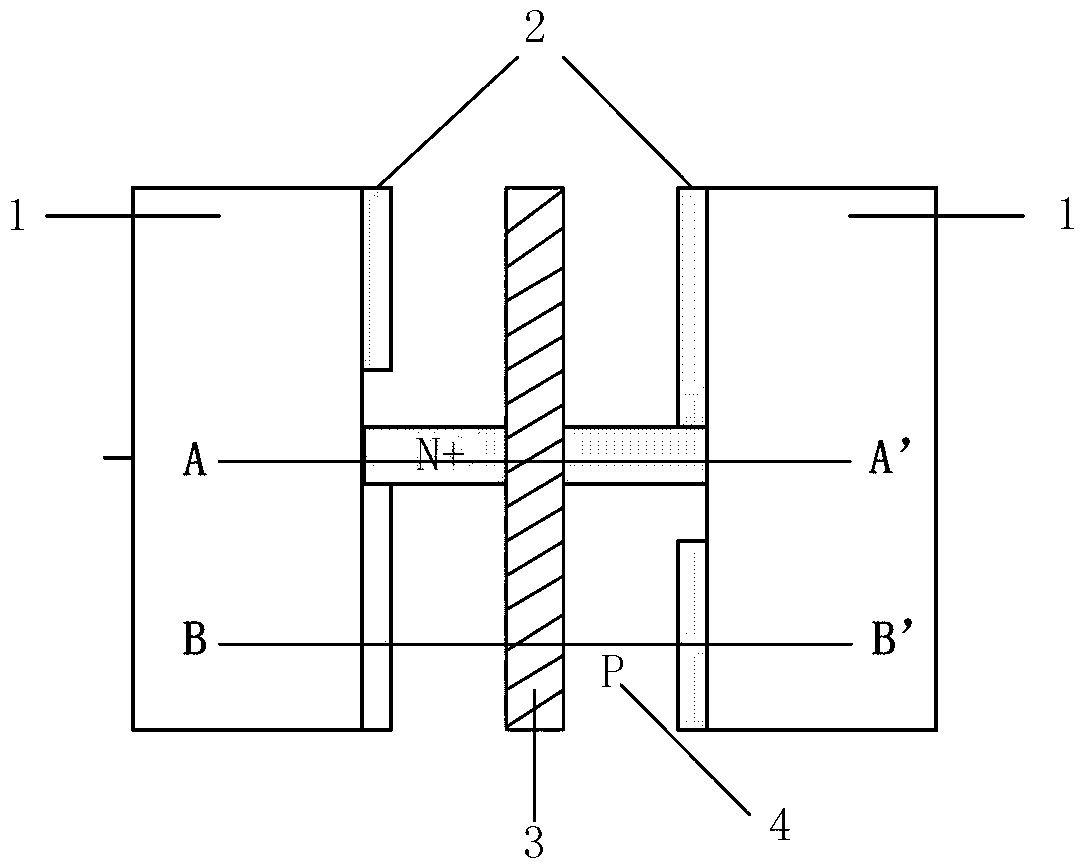
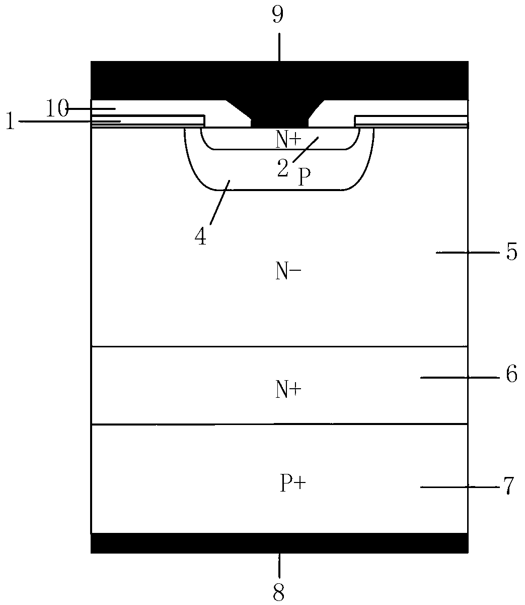
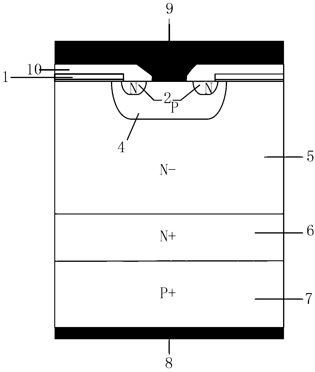
[0021] An IGBT device with positive temperature coefficient emitter ballast resistance, its layout structure is as follows Figure 4 As shown, the longitudinal section structure diagram of the corresponding A-A' unit and B-B' unit line in the layout unit is as follows Figure 5 , 6 shown, including P + Collector area 7, located at P + The metal collector electrode 8 and N on the back of the collector region 7 - Drift zone 5, located in N - Drift Zone 5 and P +The N-type buffer layer 6 between the collector regions 7; the N - The middle region of the top layer of the drift region 5 is the P-type base region 4, and the P-type base region 4 has N + Emitter 11, N + Transmitter area 11 is located by N + The contact hole 3 at the center of the emitter region 2 is connected to the metal emitter 9; the IGBT device also includes a gate structure, the gate structure is composed of a polysilicon gate electrode 1 and a gate oxide layer in contact with each other, wherein the gate ...


PUM


Abstract

The invention discloses an insulated gate bipolar transistor (IGBT) device with positive temperature coefficient emitter ballast resistance (EBR), and belongs to the technical field of power semiconductor devices. In a conventional IGBT device of an EBR structure, the EBR is composed of a strip-shaped N<+> emitter region strip, the resistance value of the EBR generally represents a negative-temperature coefficient, namely, the higher the temperature is, the smaller the resistance value is, saturation current of the IGBT is increased, and the short-circuit capacity of the IGBT device with the positive temperature coefficient EBR will be remarkably reduced in high-temperature environments. According to the IGBT device with the positive temperature coefficient EBR, deep energy level acceptor impurities, including In or Ti or Co or Ni, are doped into the N<+> emitter region, holes produced after ionization of the deep energy level acceptor impurities have a certain compensation effect on N-type impurities, positive temperature coefficient EBR is achieved, thus the resistance value of the EBR is increased along with rise of the temperature of the IGBT device, and the short circuit capacity and latch resistant capacity of the IGBT are improved.

Description

technical field [0001] The invention belongs to the technical field of power semiconductor devices, and relates to an insulated gate bipolar transistor (Insulated Gate Bipolar Transistor, IGBT). Background technique [0002] Semiconductor power devices are the basic electronic components for energy control and conversion in power electronic systems. The continuous development of power electronics technology has opened up a wide range of application fields for semiconductor power devices. MOS-type semiconductor power devices marked by IGBT, VDMOS, and CoolMOS are the mainstream of devices in the field of power electronics today. Among them, the most representative semiconductor power device is IGBT. [0003] IGBT (Insulated Gate Bipolar Transistor, Insulated Gate Bipolar Transistor) is a voltage-controlled MOS / BJT composite device. Structurally, the structure of IGBT is very similar to that of VDMOS, except that the N of VDMOS + Substrate adjusted to P + substrate, but the...

Claims


Application Information

Patent Timeline
Patent Type & Authority Applications(China)
IPC IPC(8): H01L29/739H01L29/36H01L21/331
Inventor 李泽宏单亚东宋文龙顾鸿鸣邹有彪宋洵奕
Owner UNIV OF ELECTRONICS SCI & TECH OF CHINA
Why Eureka
Eureka Blog
Learn More