Rotor of permanent magnet motor

A permanent magnet motor and rotor technology, applied in the direction of magnetic circuit rotating parts, magnetic circuits, electrical components, etc., can solve the problems of strong electromagnetic interference, large mechanical wear of the motor, low mechanical strength, etc., and achieves simple manufacturing process, high resistance Demagnetization performance, high mechanical strength effect

Active Publication Date: 2013-08-21
GUANGDONG WELLING ELECTRIC MACHINE MFG +1
View PDF10 Cites 12 Cited by
  • Summary
  • Abstract
  • Description
  • Claims
  • Application Information

AI Technical Summary

Problems solved by technology

For example, the Chinese patent application number CN200720110566.5 discloses a motor. The structure of the series motor is complicated. The rotor current is mechanically commutated through the commutator and the brush. High-speed friction occurs, which causes the motor to have large mechanical wear, high noise, strong electromagnetic interference, and easy to generate sparks
[0003] Chinese patent application number CN200580041295.6 discloses an external rotor motor, which is assembled by a cantilever beam, and the imbalance of t

Method used


Image

  • Rotor of permanent magnet motor
  • Rotor of permanent magnet motor

Examples


Embodiment Construction

[0011] In order to make the technical problems, technical solutions and beneficial effects to be solved by the present invention clearer, the present invention will be further described in detail below in conjunction with the accompanying drawings and embodiments. It should be understood that the specific embodiments described here are only used to explain the present invention, not to limit the present invention.

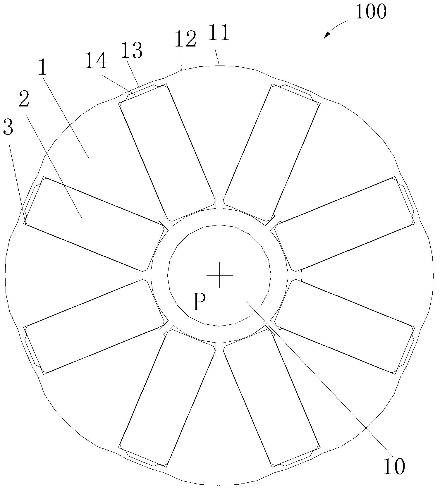
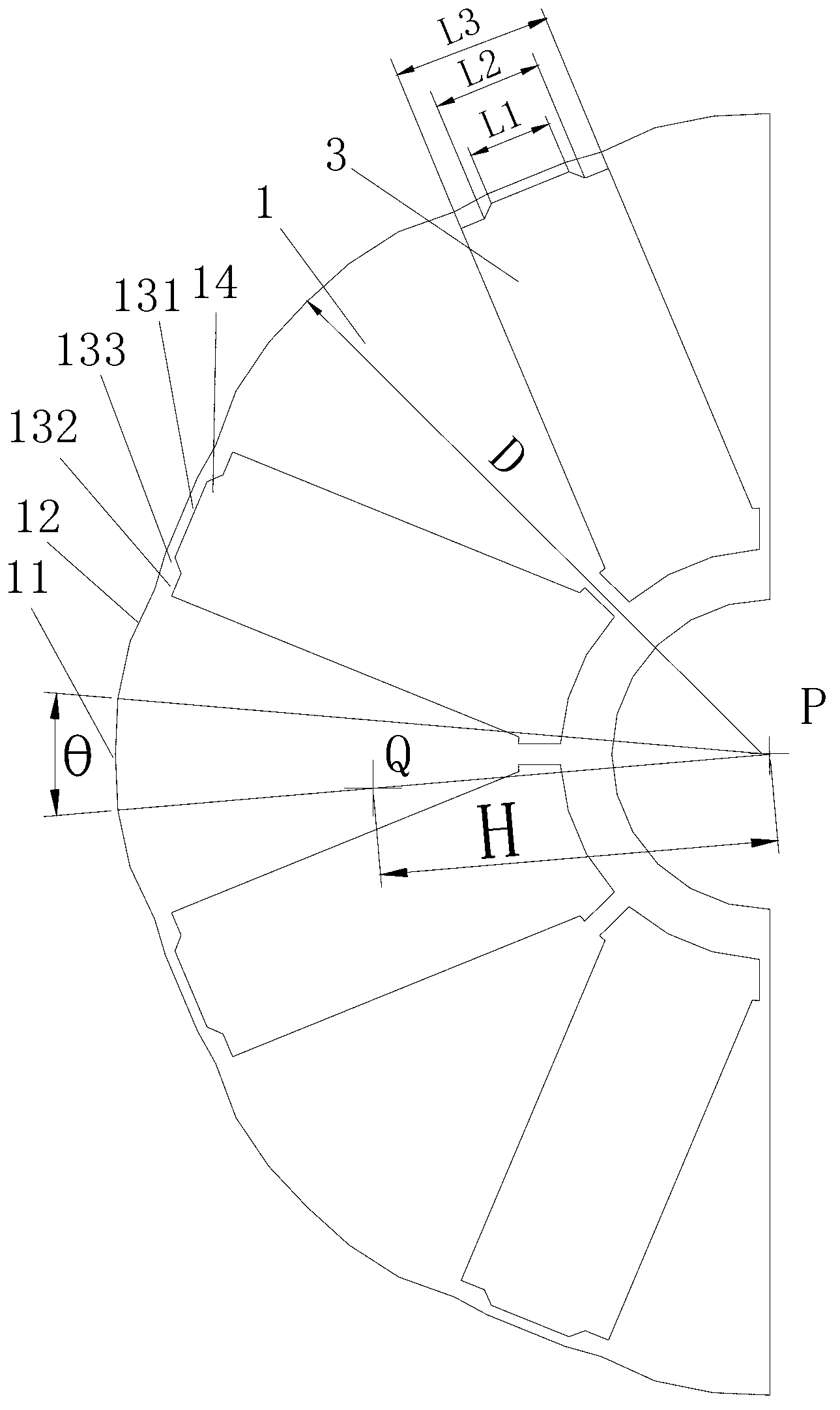
[0012] Please refer to Figure 1 to Figure 2 , is a permanent magnet motor rotor 100 of the present invention, which includes a rotor core 1 with several installation slots 3 and permanent magnets 2 installed in the installation slots 3 . Taking this embodiment as an example, the number of installation slots is 8, and in other embodiments, the number of installation slots can be 6, 10 or 12 or other numbers. The permanent magnet 2 is a ferrite structure, adopts tangential magnetization, and the magnetization directions of adjacent permanent magnets 2 are opposite....


PUM


Abstract

The invention discloses a rotor of a permanent magnet motor. The rotor comprises a rotor core with a plurality of installation grooves and permanent magnets installed in the installation grooves. The rotor core is provided with a central hole and a plurality of sections of cylindrical surfaces, a magnetic bridge is connected between adjacent cylindrical surfaces, the outside surface of each magnetic bridge is much closer to the central hole of the rotor core relative to the cylindrical surfaces, the outside surface of each magnetic bridge is outwards concave from the installation grooves to form a groove in the magnetic bridge, and the widths of the grooves are smaller than that of those of the installation grooves. Compared with the prior art, the rotor of the permanent magnet motor has the advantages that the magnetic bridges and the grooves are arranged to allow a motor with the rotor to obtain low cogging torque, reversed electromotive force tending to the sine and low load torque pulsation. The rotor has the advantages of being simple in manufacturing process, high in mechanical strength, low in noise and high in demagnetization-resistance performance due to appropriate multi-section arc or the line-section magnetic bridges, and the rotor is applicable to motors of roller washing machines.

Description

technical field [0001] The invention relates to a rotor of a permanent magnet motor, in particular to a rotor of a permanent magnet motor applied to a washing machine. Background technique [0002] At present, most of the drum washing machines use series-excited brushless motors and outer rotor brushless motors. For example, Chinese Patent Application No. CN200720110566.5 discloses a motor. The structure of the series motor is complicated. The rotor current is mechanically commutated through the commutator and brushes. When the motor is running, especially dehydration, it runs at a high speed. High-speed friction occurs, which causes the motor to have large mechanical wear, high noise, strong electromagnetic interference, and easy to generate sparks. [0003] Chinese patent application number CN200580041295.6 discloses an external rotor motor, which is assembled by a cantilever beam, and the imbalance of the external rotor causes the noise of the motor to be large. [0004...

Claims


Application Information

Patent Timeline
IPC IPC(8): H02K1/27
CPCH02K1/2773
Inventor 袁榜王飞龚文胜陈金涛诸自强
Owner GUANGDONG WELLING ELECTRIC MACHINE MFG
Why Eureka
Try Eureka