Hybrid drive device

A driving device and hybrid technology, which is applied in the direction of power devices, hybrid vehicles, pneumatic power devices, etc., can solve problems such as cost increase, second clutch slip control time becomes longer, control device problems, etc., to eliminate waste , Improve fuel utilization performance and improve reliability

Inactive Publication Date: 2013-08-28
AISIN AW CO LTD
View PDF7 Cites 6 Cited by
  • Summary
  • Abstract
  • Description
  • Claims
  • Application Information

AI Technical Summary

Problems solved by technology

[0007] Especially when the vehicle is running at extremely low speeds, when the engine drives the electric motor to charge the battery, when the engine and the electric motor are rotated at a speed equal to or higher than the speed of the input shaft based on the driving speed, it is also necessary to slip the second clutch. In this case, the slip control time of the second clutch becomes longer, which is accompanied by a problem in the control device described in the above-mentioned Patent Document 1.
[0008] In addition, it is also conceivable to directly supply lubricating oil to the second clutch for cooling (for example, refer to Patent Document 2), but in this case, flow control valves leading to each part requiring lubrication are also required, which becomes a large-scale device, resulting in rising costs

Method used


Image

  • Hybrid drive device
  • Hybrid drive device
  • Hybrid drive device

Examples


Embodiment Construction

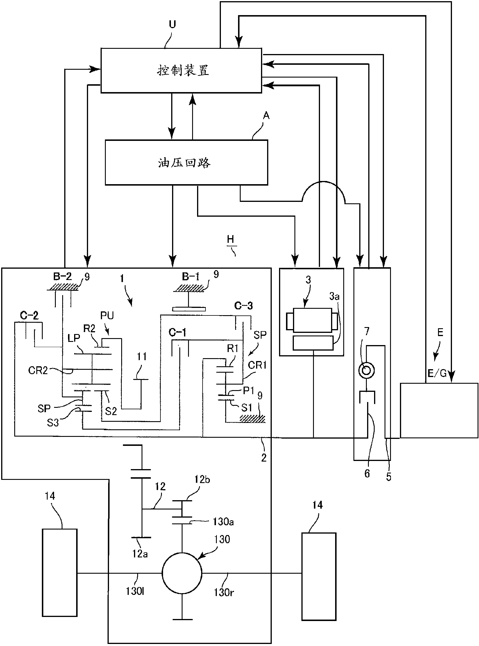
[0031] Embodiments of the present invention will be described below with reference to the drawings. Such as figure 1 As shown, the rotor 3a of the electric motor 3 is connected to the input part 2 (hereinafter referred to as the input shaft 2) of the automatic transmission 1, and the clutch 6 and the torsional vibration damper are interposed between the input shaft 2 and the engine output shaft 5 (torsion damper) 7. Therefore, this automatic transmission 1 is applied as a single-motor parallel type hybrid drive device H, and the above-mentioned electric motor 3 functions as a vehicle driving source and also as a starter (self starting motor) for starting an engine. It functions as an alternator (generator) that converts engine power or the inertial force of the vehicle into electrical energy. In addition, although the above-mentioned clutch 6 and torsional vibration damper 7 are arranged between the input shaft 2 and the engine output shaft 5, a torque converter (torque con...


PUM


Abstract

When an engine is started by an electric motor in one speed stage of an automatic transmission, lubricating oil is directly supplied to certain friction elements that control slip. A switching valve (50) branches from a lubricating oil passage (J), and is interposed on a second lubricating oil passage (J2) guided to a brake (B-2) that provides slip control when the engine starts or when a battery is charging while traveling at low speed. A hydraulic servo (39) for the brake (B-2) is linked to a control oil chamber (50a) of the switching valve (50), and when an engagement control pressure and a slip control pressure are supplied to the hydraulic servo, the switching valve (50) is switched to a linked state.

Description

technical field [0001] The present invention relates to a hybrid drive device that uses an engine and an electric motor as drive sources and transmits power to driving wheels via an automatic transmission device, and more specifically, relates to a lubrication device that directly supplies lubricating oil to friction members such as predetermined brakes of the automatic transmission device . Background technique [0002] Conventionally, in a hybrid drive system that includes a first clutch (coupling mechanism) and a second clutch (coupling mechanism, specifically, a predetermined clutch or brake of an automatic transmission), when an EV running using only an electric motor as a power source When the mode is switched to the driving mode using the engine, the first clutch is engaged to start the engine by the electric motor, the first clutch is arranged between the engine and the electric motor, and the second clutch is arranged between the electric motor and driving wheels. ...

Claims


Application Information

Patent Timeline
Patent Type & Authority Applications(China)
IPC IPC(8): B60W10/30B60K6/40B60K6/485B60K6/547B60L3/00B60L11/14B60W20/00F16H57/04B60L50/16
CPCB60L3/0023B60L15/20B60L2240/12B60L2240/423B60L2240/441B60L2240/485B60L2270/145F16H57/0435F16H57/0473F16H57/0494F16H2200/0052F16H2200/2007F16H2200/2023F16H2200/2043B60K6/365B60K6/48B60K2006/4825Y02T90/16Y02T10/72B60L50/16Y02T10/62Y02T10/64Y02T10/7072Y02T10/70
Inventor 野田和幸鬼头昌士关祐一糟谷悟
Owner AISIN AW CO LTD
Why Eureka
Try Eureka