Bone wall separation process

A bone wall and process technology, applied in the field of bone wall separation technology, can solve the problems of making the best use of materials, waste of resources, and no bone wall separation technology

Active Publication Date: 2013-09-04
哈尔滨天鹅土畜产技术开发公司 +1
View PDF7 Cites 5 Cited by
  • Summary
  • Abstract
  • Description
  • Claims
  • Application Information

AI Technical Summary

Problems solved by technology

[0002] The existing fresh bone processing technology mainly focuses on the extraction of bone glue, osteoin, bone oil, and the production of feed. At present, there is no bone wall separation process, which cannot make the best use of fine materials, thus causing waste of resources.

Method used


Image

  • Bone wall separation process
  • Bone wall separation process
  • Bone wall separation process

Examples


Embodiment approach 1

[0015] Specific Embodiment 1: This embodiment provides a bone wall separator and a method for separating a bone wall using the same.

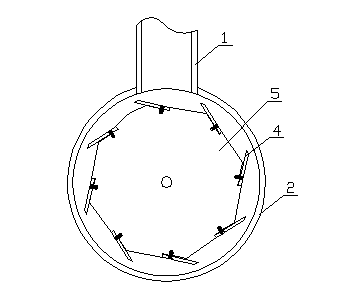
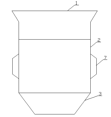
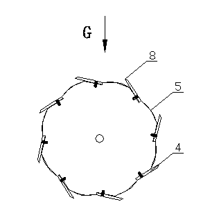
[0016] One, such as Figure 1-5 As shown, the device for separating the inner wall and the outer wall of bone by extrusion and grinding according to the present invention includes a feeding hopper 1 , a stripping chamber 2 and a discharge port 3 from top to bottom. The feeding hopper 1, the stripping bin 2, and the discharge port 3 are connected. A rotary stripping assembly is installed in the stripping chamber 2, and the rotary stripping assembly is composed of 6-12 blades 4 and a rotating shaft 5. The axis of the rotating shaft 5 is located on the transverse centerline of the stripping chamber 3; the axial surface of the rotating shaft 5 is along the circumferential direction A number of inclined blades 4 are evenly arranged and their cutting edges 8 are exposed outwards. The cutting edges 8 are adjustable by 2-10mm higher than the rotating ...

specific Embodiment approach 2

[0028] Specific embodiment two: the difference between this embodiment and specific embodiment one is that this embodiment provides a bone wall separation process after slaughtering and dividing fresh bones to extract bone collagen liquid, and the specific steps are as follows:

[0029] (1) Extraction of bone collagen solution:

[0030] (1) After soaking, rinsing, cutting into pieces and freezing the fresh bone, put it into an extraction tank and seal it;

[0031] (2) Start the vacuum pump, open the valve connected to the buffer tank, make the buffer tank negative pressure, and turn off the vacuum pump when the vacuum degree is 14-75mmhg;

[0032] (3) Open the steam valve in the extraction tank, be warming up to indicate that the temperature is 20-50 ° C, and when the pressure in the tank is 0.01-0.1MPA, close the intake valve;

[0033] (4) Gradually open the valve of the buffer tank connected to the extraction tank, pump the blood melted from the bone into the buffer tank, w...


PUM


Abstract

The invention discloses a bone wall separation process which comprises the steps as follows: 1), fresh bones or bone residues from which collagen protein fluids are extracted are placed into a cleaning tank and cleaned, then are fished out and drained; 2), the drained bone residues are fed into a grinder for coarse grinding; and 3), the bone residues which are subjected to coarse grinding are fed into a bone wall separator for bone wall stripping, and the stripped bone residues are transmitted to a three-layer sieving machine for sieving. According to the process, after separation, an outer bone wall, namely, a compact bone substance, is high in mineral content and suitable for being used as a raw material of a calcium supplement preparation, and the additional value is increased; during separation, a mixed part of an inner bone wall and the outer bone wall exists in a middle stage and can be taken as a pet feed supplement; and after separation, the inner bone wall, namely, a cancellous substance, collected blood-containing waste water in a slaughter house, blood dripped from a rag and blood water pumped before extraction of collagen protein mixed fluids from the fresh bones are mixed uniformly, subjected to enzymolysis and fermentation and used for producing a bone blood peptide microorganism organic fertilizer, so that all the substances are consumed fully.

Description

technical field [0001] The invention relates to a bone wall separation process. Background technique [0002] Existing fresh bone processing technology is mainly focused on extracting bone glue, osteoin, bone oil, and producing feed. At present, there is no bone wall separation process, which cannot make the best use of fine materials, thus causing waste of resources. Contents of the invention [0003] In order to make full use of the bone slag, the present invention provides a bone wall separation process by using the dense and sparse structure characteristics of the outer layer and the inner layer of the bone wall, through which the best use of all materials can be realized, and the economic benefits of deep processing of slaughtering waste can be increased. [0004] Bone wall separation process of the present invention, comprises the steps: [0005] (1) Put the fresh bones or the remaining bone dregs after extracting the bone collagen solution into the cleaning tank fo...

Claims


Application Information

Patent Timeline
IPC IPC(8): A23L1/312A23L1/29A23K1/10C05F7/00A23L13/20A23L33/00
CPCY02A40/20
Inventor 牟钰德赵思雨赵伟洁
Owner 哈尔滨天鹅土畜产技术开发公司
Why Eureka
Try Eureka