Solar photocatalytic oxidation-membrane separation three-phase fluidized bed circulation reaction apparatus

A three-phase fluidized bed and photocatalytic reaction technology, applied in the field of reaction devices, can solve the problems of difficult catalyst replacement, film shedding, low light utilization rate, etc., achieve high mass transfer efficiency and light energy utilization rate, and facilitate operation and maintenance , The effect of increasing the amount of wastewater treatment

Inactive Publication Date: 2013-09-04
TIANJIN POLYTECHNIC UNIV
View PDF4 Cites 7 Cited by
  • Summary
  • Abstract
  • Description
  • Claims
  • Application Information

AI Technical Summary

Problems solved by technology

Its biggest feature is that it does not need to separate the catalyst, but the mass transfer is limited and the reactor processing capacity is small
[0007] (3) Packed bed photocatalytic reaction device: This type of reaction device is usually filled with titanium dioxide particles or silica gel, alumina, quartz sand and glass beads coated with a titanium dioxide film on the surface of the reaction device, which can effectively allow light to pass through, and With a high specific surface area, the reaction is not limited by mass transfer, but the disadvantage is that the collision between particles may cause the film to fall off, the utilization rate of light is low, and the replacement of the catalyst is very difficult
However, the upper water tank and the membrane separator shell are respectively set in the reaction device, which makes the structure of the reaction device more complicated; and the second aeration device needs to be installed at the bottom of the membrane module to slow down or prevent membrane fouling, resulting in higher energy consumption

Method used


Image

  • Solar photocatalytic oxidation-membrane separation three-phase fluidized bed circulation reaction apparatus
  • Solar photocatalytic oxidation-membrane separation three-phase fluidized bed circulation reaction apparatus
  • Solar photocatalytic oxidation-membrane separation three-phase fluidized bed circulation reaction apparatus

Examples


Embodiment Construction

[0037] The present invention will be described in detail below in conjunction with the specific implementation of Example 1 and Example 2.

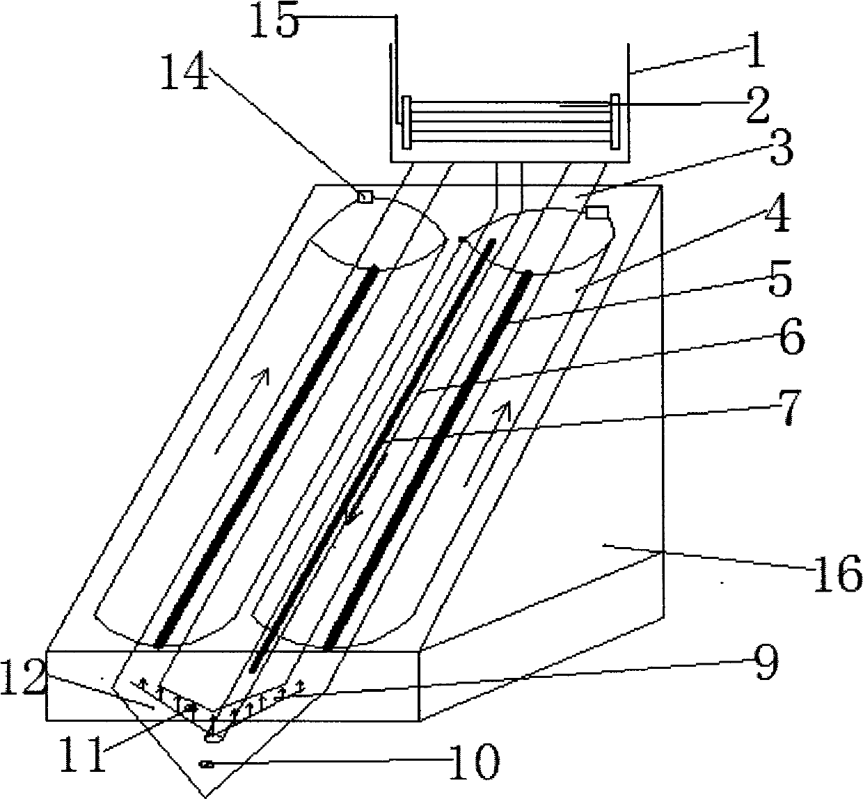
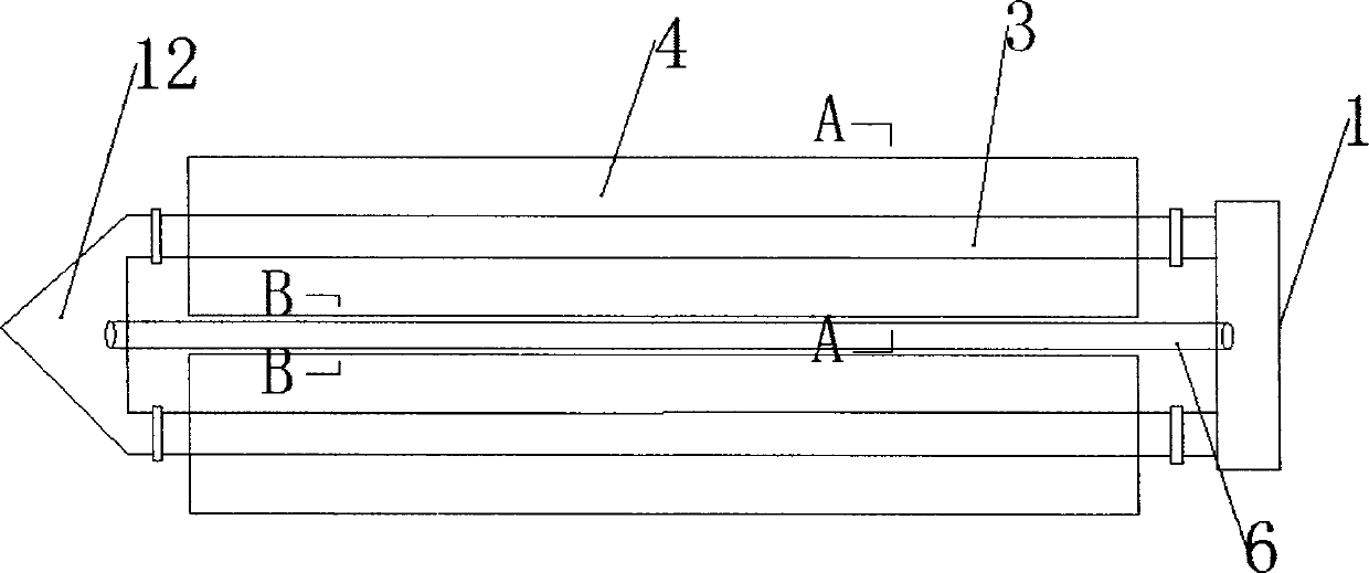
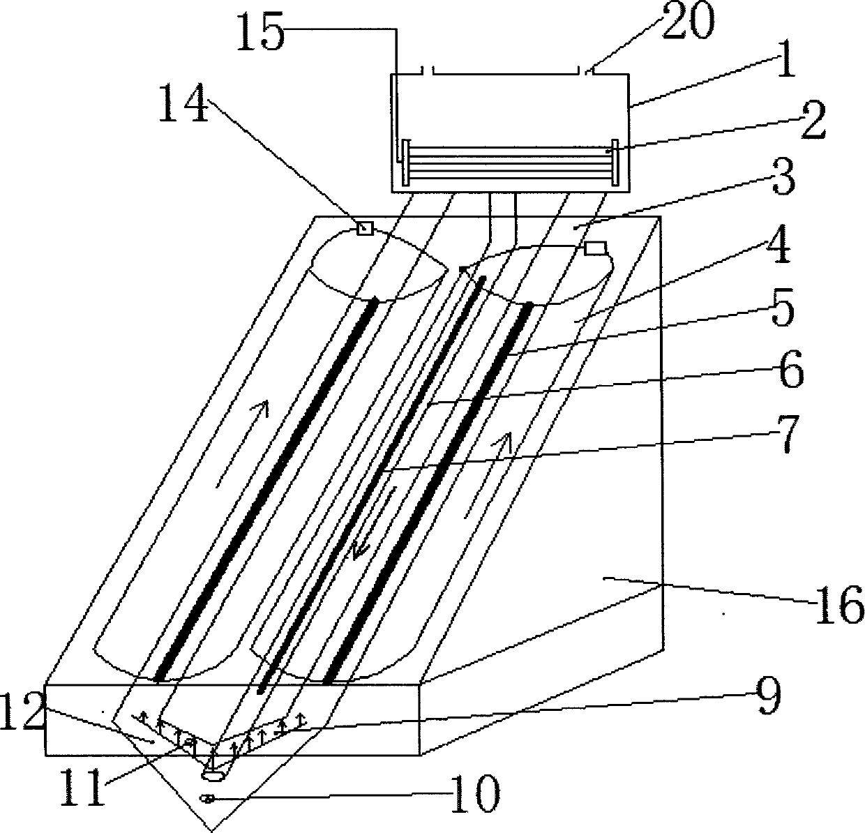
[0038] The solar photocatalytic oxidation-membrane separation three-phase fluidized bed circulation reaction device of the present invention as shown in the accompanying drawings, it includes a photocatalytic reaction zone and a membrane separator, and the photocatalytic reaction zone includes a lighting system, a tubular reaction device 3 and lower water tank 12; wherein the daylighting system includes a daylighting panel 4 and a solar tracking device 14, and wherein the daylighting panel 4 can be a truncated compound parabolic daylighting panel or a solar energy concentrating panel, and Described truncated compound parabolic daylighting panel or sunlight concentrating panel 4 are arranged on the rotating shaft controlled by sunlight automatic tracking device 14 according to needs; Set, at this moment daylighting system is only made up o...


PUM


Abstract

The invention discloses a solar photocatalytic oxidation-membrane separation three-phase fluidized bed circulation reaction apparatus. The apparatus comprises a photocatalytic reaction area and a membrane separator, wherein the photocatalytic reaction area comprises a lighting panel (a truncation type compound parabolic lighting panel or a solar energy gathering panel), a solar tracking device, a tubular reactor, a lower water tank, and a first aerating device, the membrane separator comprises a membrane separator shell and a membrane component, a second aerating device can be arranged on the bottom of the membrane component according to need, the solar tracking device can be eliminated according to need, the membrane separator shell is an opening type shell or a closed type shell with an exhaust device, and heating devices can be arranged in the lower water tank, the membrane separator shell and the circulating pipe according to need. The solar photocatalytic oxidation-membrane separation three-phase fluidized bed circulation reaction apparatus disclosed by the invention not only can be used for carrying out a photocatalytic oxidation reaction, but also can be used for carrying out a photo-thermal synergetic catalytic oxidation reaction.

Description

technical field [0001] The present invention relates to a kind of reaction device, and the present invention especially relates to a kind of solar photocatalytic oxidation wastewater treatment device not affected by weather: solar photocatalytic oxidation-membrane separation three-phase fluidized bed circulation reaction device (following reaction device), the The device can be applied not only to the pretreatment or advanced treatment of toxic and harmful refractory organic wastewater, but also to the advanced treatment of slightly polluted drinking water. Background technique [0002] With the rapid development of my country's social economy, a large amount of waste pollutants are inevitably produced, which leads to serious environmental pollution and ecological damage. Traditional treatment methods cannot completely eliminate degradation pollutants, and are likely to cause secondary pollution, with narrow application range and high energy consumption. In recent years, th...

Claims


Application Information

Patent Timeline
Patent Type & Authority Applications(China)
IPC IPC(8): C02F9/04C02F1/44
CPCY02W10/37
Inventor 解立平岳俊楠申春苗杨明沁
Owner TIANJIN POLYTECHNIC UNIV
Why Eureka
Try Eureka