Steel belt butt-joint device and butt-joint method thereof

A technology of butt joints and steel strips, applied in the direction of thin plate connection, connecting components, metal rolling, etc., can solve the problem of increasing the gap between the end cover and the base and the overall thickness of the fixture, increasing labor intensity and working time, fixture and sealing Problems such as roller contact and collision can be eliminated to achieve the effect of improving unit operation rate, shortening operation time and shortening connection time

Active Publication Date: 2015-06-03
ANGANG STEEL CO LTD
View PDF7 Cites 0 Cited by
  • Summary
  • Abstract
  • Description
  • Claims
  • Application Information

AI Technical Summary

Problems solved by technology

The through hole of the steel belt connection fixture is a round hole, and the inner diameter is 18mm round steel to increase the resistance strength, resulting in an increase in the overall height of the fixture
Due to the unavoidable fluctuations during the operation of the steel belt connected by the fixture, when passing through a narrow area such as the sealing roller of the continuous furnace annealing of the unit, it is easy to cause contact and collision between the fixture and the sealing roller, resulting in a secondary broken belt accident
[0005] 2. The locking force of the steel belt is not enough, and it is easy to cause the lead or the tail to fall off.
Because the head and the tail of the connection fixture are matched with the round hole through the round steel, it is "locked" by the action of external force. If the locking force is insufficient, the round steel in the through hole will slip, resulting in joint failure
[0006] 3. The operation is time-consuming and labor-intensive, which affects the operation efficiency
First, because the connecting jig needs double-layer winding, folding and extruding of the steel strip, it not only occupies the space in the through hole, but also increases the gap between the end cover and the base and the overall thickness of the jig; and when the double-layer steel strip is bent, To overcome the deformation strength of the steel strip itself, it is time-consuming and labor-intensive, increasing labor intensity and working time

Method used


Image

  • Steel belt butt-joint device and butt-joint method thereof
  • Steel belt butt-joint device and butt-joint method thereof

Examples


Embodiment Construction

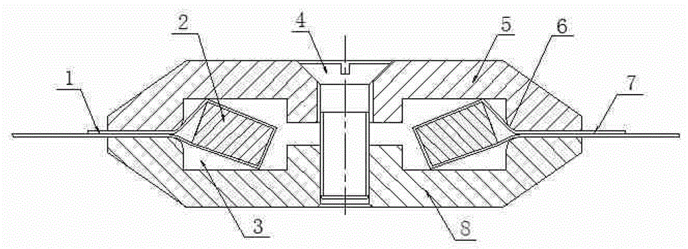
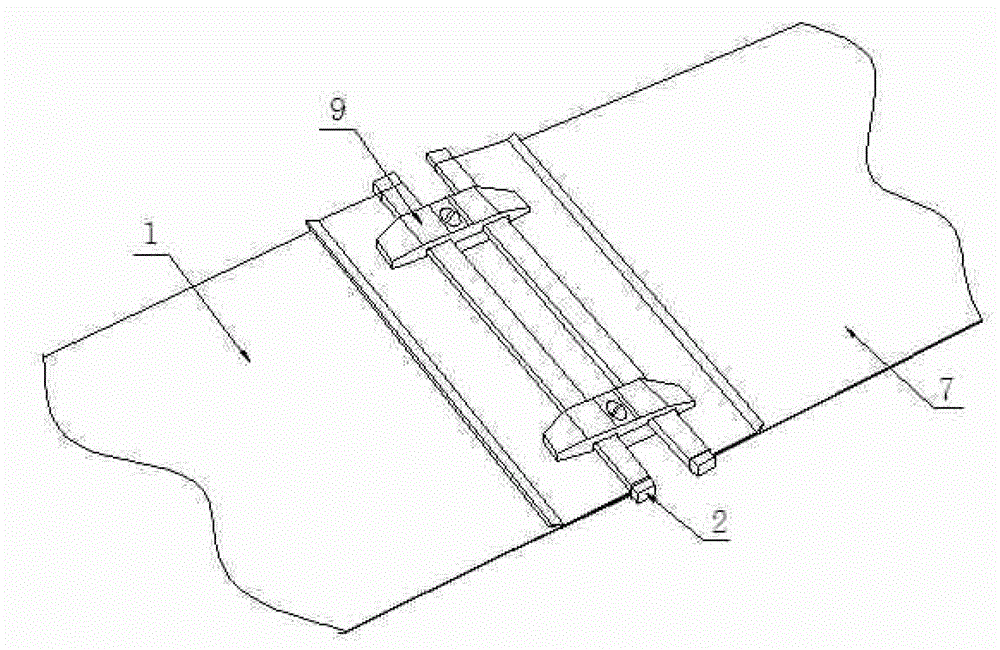
[0029] The steel belt butt joint of the present invention is mainly composed of reinforced square steel rod 2, countersunk head bolt 4, end cover 5 and base 8. The overall shape and size of end cover 5 and base 8 are the same, and they are all flat trapezoidal platforms.

[0030] On the trapezoidal table working surface of the end cover 5 and the base 8, there are two rectangular through grooves with a depth of 5 mm symmetrically. In order to avoid scratching the steel strip, a chamfer 6 is processed on the inner side of the outer wall of the through groove. There is a countersunk bolt hole in the center of the trapezoidal table. The end cover 5 and the base 8 are connected together by the countersunk bolt 4. After the buckle, the through groove of the end cover 5 and the base 8 forms two rectangular through holes 3. , A reinforced square steel rod 2 with a section size of 15×10mm is arranged in the through hole 3 .

[0031] Taking the continuous annealing unit of cold-rolled ...


PUM


Abstract

The invention provides a steel belt butt-joint device and a butt-joint method thereof. The steel belt butt-joint device and butt-joint method thereof comprises at least two groups of end covers, a base and a countersunk bolt. Two through grooves are formed on the working faces formed by the end covers and the base, and two rectangular through holes are formed after opposite buckling. When steel belt butt joint is performed, a hand hammer is utilized to fix steel belts on a reinforced square steel rod, belt heads and belt tails are placed into the through holes, the countersunk bolt is fastened appropriately to exert tensile force on the belt heads and the belt tails respectively and then is fastened after tightening to exert tensioning force, and the belt heads and the belt tails are firmly clamped on inner walls of the through holes through the reinforced square steel rod. The height of the butt-joint device can be reduced, so that the butt-joint device can conveniently and smoothly pass through the sealing roller position and other narrow regions, and belt breakage accidents are avoided. The steel belts are formed through single-layer extrusion, so that the labor intensity is reduced, the operation time is shortened, and the operation efficiency is improved by more than 30%. Friction resistance is increased through external force, the locking effect is guaranteed, the steel belt connecting success rate and the unit operation rate are improved, and the production cost is reduced. The steel belt butt-joint device is simple in structure, convenient to operate and strong in applicability.

Description

technical field [0001] The invention belongs to the field of steel rolling machinery, and in particular relates to a head-tail connection device and a connection method for a broken cold-rolled sheet steel strip of a continuous annealing unit. Background technique [0002] In the production process of cold-rolled galvanized continuous annealing and silicon steel continuous annealing units, the steel strip running at high speed often has accidental "broken belt" accidents, so that the entire galvanizing or annealing unit has to be forced to stop production. The conventional steel belt connection method is: the belt head and the belt tail of the two broken belts are lapped together by jogging the transmission roller, and then the joint operation is carried out by spot welding with an argon arc welding machine. However, before argon arc welding, operations such as trimming and leveling of the steel strip surface are required, so the operation time is long, which affects the ope...

Claims


Application Information

Patent Timeline
Patent Type & Authority Patents(China)
IPC IPC(8): F16B5/06B21B15/00
Inventor 付文旭刘立新李元华张勇
Owner ANGANG STEEL CO LTD
Why Eureka
Try Eureka