Continuous exhaust unit flue gas system

A technology for continuous withdrawal of units and flue gas, applied in furnace components, climate sustainability, waste heat treatment, etc., can solve the problems of unutilized sensible heat of exhaust flue gas, waste of waste heat resources, and increased fan output, etc. The effect of safety and reliability, energy saving and output reduction

Active Publication Date: 2015-08-19
BAOSTEEL ENG & TECH GRP
View PDF5 Cites 0 Cited by
  • Summary
  • Abstract
  • Description
  • Claims
  • Application Information

AI Technical Summary

Problems solved by technology

[0004] The main disadvantages of the above-mentioned existing flue gas system of the continuous cooling unit are as follows: the sensible heat in the exhaust flue gas is not used, and a large amount of waste heat resources are wasted; At 400°C, a certain amount of cold air needs to be added to ensure the stable, safe and reliable operation of the induced draft fan 1'. This situation will increase the output of the fan and cause power waste

Method used


Image

  • Continuous exhaust unit flue gas system
  • Continuous exhaust unit flue gas system

Examples


Embodiment Construction

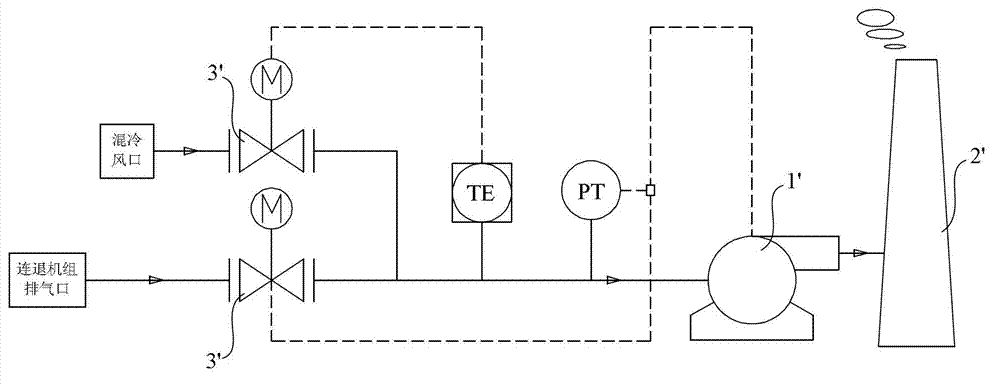
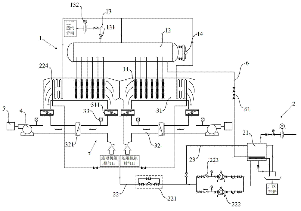
[0031] The flue gas system of the continuous degassing unit proposed by the present invention will be further described in detail below in conjunction with the accompanying drawings and specific embodiments. Advantages and features of the present invention will be apparent from the following description and claims. It should be noted that the drawings are all in a very simplified form and use imprecise ratios, which are only used to facilitate and clearly assist the purpose of illustrating the embodiments of the present invention.

[0032] The core idea of ​​the present invention is to provide a flue gas system of a continuous cooling unit, which includes a heat pipe waste heat recovery device, a water supply system, a flue gas pipeline and an induced draft fan, one end of the flue gas pipeline is connected to the exhaust port of the continuous cooling unit , the other end of the flue gas pipe is connected to the induced draft fan, the induced draft fan is connected to the chi...


PUM


Abstract

The invention provides a flue gas system for a continuous annealing unit. The flue gas system comprises a heat pipe waste heat recovery device, a water supply system, a flue gas pipeline and an induced draft fan, wherein one end of the flue gas pipeline is connected with an exhaust port of the continuous annealing unit, the other end of the flue gas pipeline is connected with the induced draft fan which is connected with a chimney, the heat pipe waste heat recovery device is arranged in the flue gas pipeline, and the water supply system is connected with the heat pipe waste heat recovery device which provides low-pressure steam for a factory. According to the flue gas system for the continuous annealing unit, sensible heat in flue gas of the continuous annealing unit can be converted into the low-pressure steam to be used by units of the factory under the condition that an original combustion control mode is unchanged, usage of external steam can be reduced, and energy saving and emission reduction can be achieved.

Description

technical field [0001] The invention relates to a flue gas waste heat recovery system, in particular to a flue gas system of a continuous aeration unit. Background technique [0002] In the prior art, the heating section of the general continuous cooling unit is divided into 8 heating zones, and the flue gas is divided into two independent flues (that is, 4 zones and 1 flue gas channel) to be discharged through the chimney of the induced draft fan. The heating zone adopts the radiant heating method, that is, the gas burns in the radiant tube, and the steel strip is heated through the radiant tube. The general flue gas discharge temperature is between 400°C and 700°C. Because this heating method has negative pressure on the combustion in the radiant tube The control requirements are extremely high, so the flue gas exhausted by general heating furnaces has not been recovered for waste heat. [0003] figure 1 It is a structural schematic diagram of the flue gas system of the ...

Claims


Application Information

Patent Timeline
Patent Type & Authority Patents(China)
IPC IPC(8): F27D17/00F22B1/18
CPCY02P10/25Y02P80/15
Inventor 方国红施国华朱文君
Owner BAOSTEEL ENG & TECH GRP
Why Eureka
Try Eureka