Damping force controllable viscous damper and intelligent monitoring and control system of damping force controllable viscous damper

A viscous damper and damper technology, applied in the field of structural shock absorption, can solve the problems of poor temperature stability, influence of engineering structure safety, small tension, etc., to avoid attenuation and distortion, good shock absorption protection effect, and effective implementation control effect

Inactive Publication Date: 2013-09-11
HUAZHONG UNIV OF SCI & TECH
View PDF6 Cites 9 Cited by
  • Summary
  • Abstract
  • Description
  • Claims
  • Application Information

AI Technical Summary

Problems solved by technology

Although silica gel has good viscosity-temperature resistance, moisture-proof and electrical insulation, and small compression deformation, it has defects such as poor temperature stability; silicone oil has good heat resistance, oxidation resistance, and low temperature resistance, and is not volatile and compression-resistant. Strong force means small tension and chemical stability, so it is currently the mainstream viscous energy-dissipating material in the industry
[0004] However, the working speed of the viscous damper in the prior art is pre-designed, once the vibration of the structural engineering is greater than the design value of the viscous damper, it may cause damage to the damper and affect the safety of the engineering structure. In addition, when the viscous damper is installed on the structural engineering, the vibration force and displacement of the engineering structure cannot be effectively monitored, so that the vibration state of the engineering structure cannot be monitored and monitored in a timely and effective manner. Corresponding control

Method used


Image

  • Damping force controllable viscous damper and intelligent monitoring and control system of damping force controllable viscous damper
  • Damping force controllable viscous damper and intelligent monitoring and control system of damping force controllable viscous damper

Examples


Embodiment Construction

[0030] In order to make the object, technical solution and advantages of the present invention clearer, the present invention will be further described in detail below in conjunction with the accompanying drawings and embodiments. It should be understood that the specific embodiments described here are only used to explain the present invention, not to limit the present invention.

[0031] In view of the fixed working speed of various viscous dampers in the prior art, once the vibration of the structural engineering is greater than the design value of the viscous damper, it may cause damage to the damper and have a great impact on the safety of the engineering structure , the present invention expects to make corresponding improvements to this type of viscous damper, so as to realize effective control of the damping force of the damper.

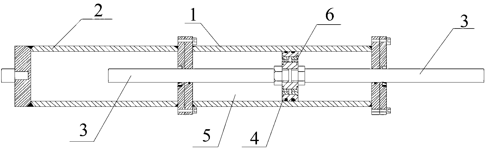
[0032] figure 1 It is a schematic diagram of the overall structure of the viscous damper with controllable damping force according to the p...


PUM


Abstract

The invention discloses a damping force controllable viscous damper and an intelligent monitoring and control system of the damping force controllable viscous damper. The damper comprises a cylinder body, a piston and a piston rod, wherein the interior of the cylinder body is divided into a main cylinder and an auxiliary cylinder; the main cylinder is filled with a damping medium formed by polyethylene glycol and nanoscale silica particles; the silica particles are suspended and dispersed in polyethylene glycol in a fluid state; the piston is arranged in the main cylinder and can move back and forth in the axial direction of the main cylinder so as to drive the piston rod connected with the piston to move together; one end of the piston rod penetrates through a damping hole formed in the piston; and the other end of the piston rod extends into the auxiliary cylinder. The invention further discloses the corresponding intelligent monitoring and control system. With the adoption of the damper and the system, the damping force of the damper can be effectively controlled, and the operating state of the damper can be detected, fed back and adjusted in real time, so that the safety of an engineering structure is better protected.

Description

technical field [0001] The invention belongs to the technical field of structural shock absorption, and more specifically relates to a viscous damper with controllable damping force and an intelligent monitoring and control system thereof. Background technique [0002] A damper is a device that provides movement resistance to consume movement energy. Since the 1970s, damping technology has been gradually used in structural engineering such as buildings, bridges, and railways, and has achieved rapid development. At present, dampers are mainly divided into spring dampers, hydraulic dampers, rotary dampers, viscous dampers, etc. Among them, the working principle of viscous dampers is based on fluid movement, especially when fluid passes through an orifice. The damper made of the effect of resistance. Because of its indeterminate stiffness, good weather resistance, and the ability to reduce both structural stress and reaction displacement, it is widely used in high-rise buildi...

Claims


Application Information

Patent Timeline
Patent Type & Authority Applications(China)
IPC IPC(8): F16F9/18F16F9/508F16F9/32
Inventor 袁涌资道铭朱宏平崔文社
Owner HUAZHONG UNIV OF SCI & TECH
Why Eureka
Try Eureka