Charging circuits for energy storage apparatus and method for charging for energy storage apparatus

An energy storage device and charging circuit technology, which is applied in the field of charging circuits, can solve the problems of energy supply phase efficiency reduction, failure of the entire phase, system failure, etc., to reduce the installation space requirements, the total system volume, and the device requirements. Effect

Active Publication Date: 2013-09-11
ROBERT BOSCH GMBH
View PDF5 Cites 5 Cited by
  • Summary
  • Abstract
  • Description
  • Claims
  • Application Information

AI Technical Summary

Problems solved by technology

[0004] The series connection of multiple battery modules poses the problem that when only one battery module fails, the entire phase fails
Such a failure of the energy supply phase can lead to failure of the entire system
Furthermore, a temporary or permanent reduction in the efficiency of individual battery modules leads to a reduction in the efficiency of the entire energy supply phase

Method used


Image

  • Charging circuits for energy storage apparatus and method for charging for energy storage apparatus
  • Charging circuits for energy storage apparatus and method for charging for energy storage apparatus
  • Charging circuits for energy storage apparatus and method for charging for energy storage apparatus

Examples


Embodiment Construction

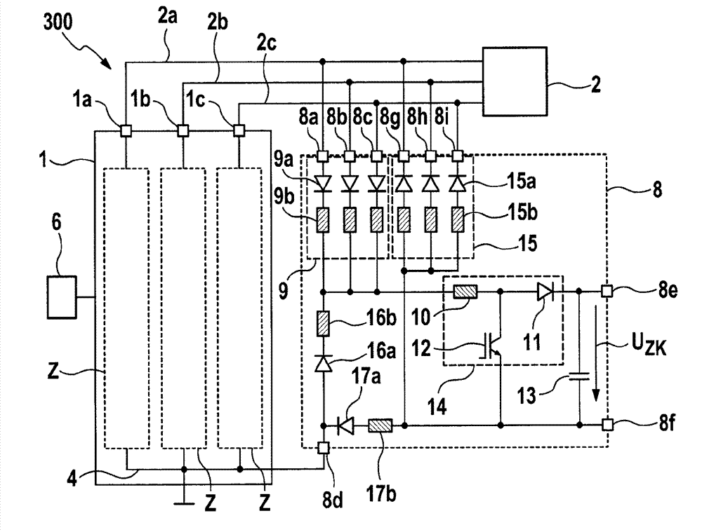
[0038] figure 1 A schematic diagram of a system 100 with an energy storage device 1 for converting a DC voltage provided in an energy storage module 3 into an n-phase AC voltage is shown. The energy storage device 1 includes a plurality of energy supply branches Z, in which figure 1 Three energy supply branches Z are shown by way of example, which are suitable for generating, for example, a three-phase AC voltage for a three-phase electric machine 2 . However, it is clear that any other desired number of energy supply branches Z would also be possible. The energy supply branch Z may have a plurality of energy storage modules 3 connected in series to form the energy supply branch Z. For example, in figure 1 Three energy storage modules 3 per energy supply branch Z are shown in , however any other number of energy storage modules 3 would also be possible. At each of the energy supply branches Z, the energy storage device 1 has an output connection 1 a , 1 b and 1 c which are...


PUM


Abstract

The invention relates to charging circuits (30 and 40) for an energy storage apparatus (1). The charging circuit (30 and 40) comprises a first half-bridge circuit (9), a second half-bridge circuit (15), first feed nodes (37a, 37b and 47a), second feed nodes (37a, 37b and 47a), feed circuits (35; 44 and 45), converter inductance coils (31 and 41), a semiconductor switch (33) and compensation diodes (16a and 17a).

Description

technical field [0001] The invention relates to a charging circuit for an energy storage device and a method for charging the energy storage device, in particular to a method for charging a battery direct inverter with direct current voltage. Background technique [0002] It can be seen that electronic systems combining new energy storage technologies with electric drive technology will be increasingly used in the future not only in stationary applications such as wind power plants or solar power plants, but also in vehicles such as hybrid or electric vehicles. [0003] The feeding of the multiphase current into the electrical machine is usually realized with a converter in the form of a pulse width modulated inverter. For this purpose, the DC voltage provided by the DC link circuit can be converted, for example, into a multiphase AC voltage, for example a three-phase AC voltage. In this case, the DC link circuit is fed by a phase formed by series-connected battery modules....

Claims


Application Information

Patent Timeline
Patent Type & Authority Applications(China)
IPC IPC(8): H02J7/00H01M10/44B60L11/18H02M3/155
CPCH01M10/46H01M10/441H01M2220/20B60L2210/14B60L2210/30B60L2210/42Y02T90/14H02J7/0013H02J7/0024Y02T10/92Y02T10/7072B60L53/22B60L58/18B60L58/21Y02T10/70Y02T10/72Y02E60/10
Inventor H.拉普
Owner ROBERT BOSCH GMBH
Why Eureka
Try Eureka